Before starting – O.S. Engines 65LA User Manual
Page 11
Finally, secure the complete assembly to rear cover
plate as before.
3.
As self-tapping screws are used for unit
attachment, screw them in carefully so that screw
threads match those of the unit body precisely.
Note:
Remove the two cover-plate screws which secure
the needle-valve assembly bracket, then carefully
remove the two screws by which the needle-valve
unit is attached to the bracket.
Rotate the needle-valve unit through 90˚ and re-
attach it to the bracket in the required position (see
sketch right ).
Vertical position
(Factory position)
Horizontal position
Cover plate fitting holes
Needle Valve unit
Needle Valve unit attachment screws
Needle-Valve
Assembly Bracket
1.
2.
BEFORE STARTING
Tools, accessories, etc.
The following items are necessary for operating the
engine.
1 Fuel
Model glowplug engine fuel of good quality, preferably
containing a small percentage of nitromethane. (See
"Advice on selection of fuel, glowplug and propeller")
2 Glowplug
O.S. A3 glowplug is installed in the engine.
3 Propeller
Suggested size is 11X5 (40LA), 11 X6 (46LA), or 12 X6
(65LA).
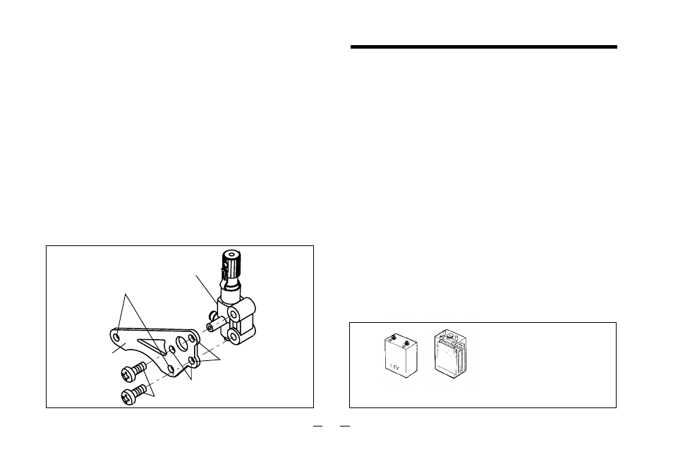
4 Glowplug battery
The power source for heating the glowplug may be
either a large heavy-duty 1.5volt dry cell, or preferably,
a 2-volt rechargeable lead-acid cell (accumulator).
1.5 volt heavy-duty
dry battery
or 2 volt rechargeable
lead-acid cell (at least 5Ah)
If a 2-volt cell is employed,
use a resistance wire, as
shown, to reduce applied
voltage, otherwise the element
will overheat and burn out.
10