1 cable connection guide, 3 2.1 c – NORAC UC4+BC+CBL User Manual
Page 7
3
2.1 C
ABLE
C
ONNECTION
G
UIDE
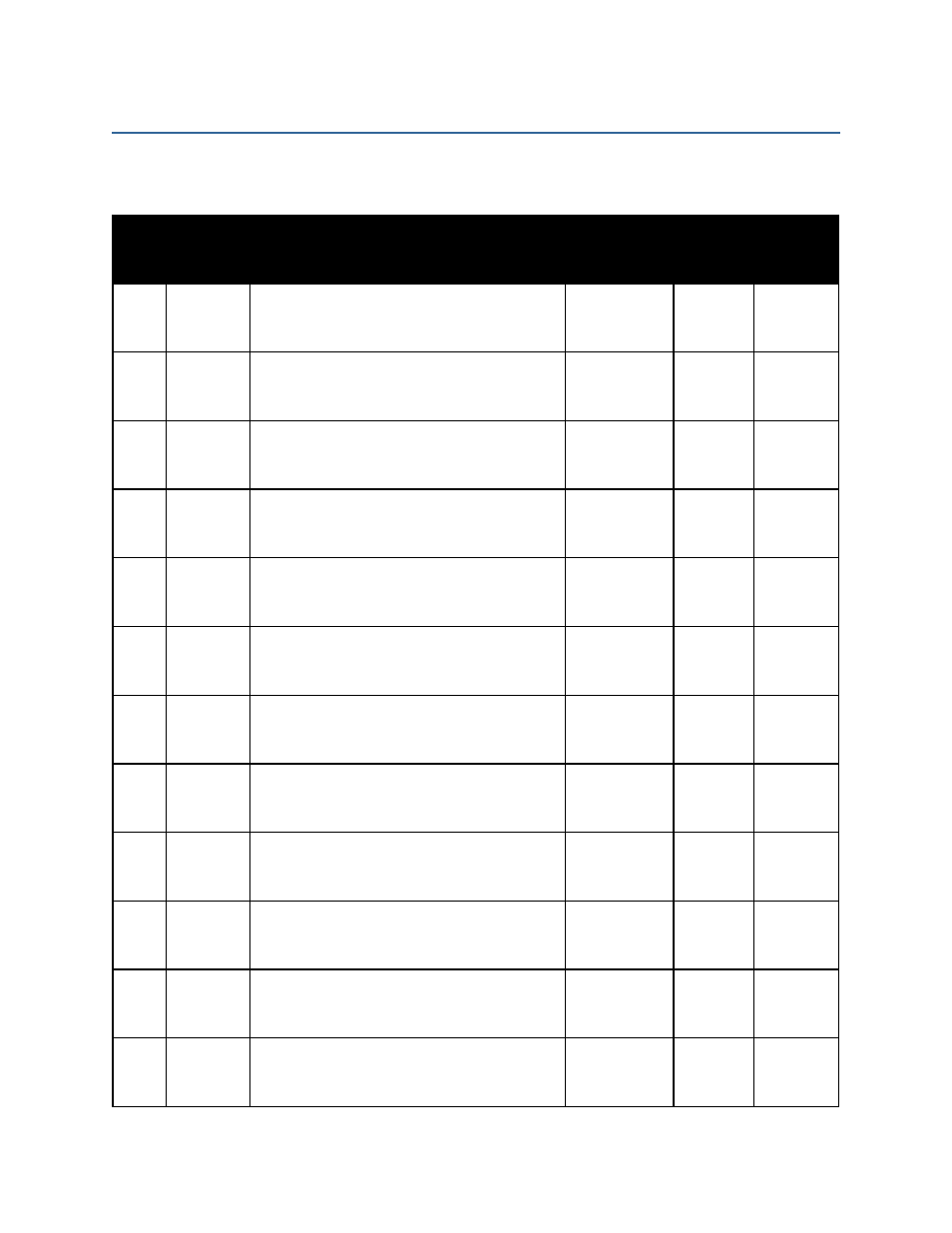
The following table shows the cables that are required for the main connections in the UC4.5
system. Refer to Figure 1 for the location of each cable by item number.
Item
Part
Number
Description
Available
Lengths
Typical
Length
Quantity
Needed
C02
44668
Height Sensor Connections:
Sensor Branch Cable
1
C02B
44664
Roll Sensor Connections:
Roll Sensor Cable
(This cable is not always required)
1
C03
44656D
NORAC Valve Block to Valve Extension Cable:
NORAC Valve Cable
1
C10
44650-35
44650-39
Control Panel to Valve Extension Cable: Main
Power Cable
1
C11
44651-03
Main Cable to Sensors and Interface Cables:
Valve Extension Cable
1
C12
Various
Valve Extension Cable to Sprayer Valve Block:
Valve Interface Cable
1
C13
Various
Valve Extension Cable to Sprayer Valve Block:
Bypass/Remote Manual Interface Cable
(This cable is not always required)
Various
1.5 m
1
C14
Various
Main Power Cable to Sprayer Power:
Battery Cable
Various
1
C15
Various
Main Power Cable to Remote Switches:
NORAC Switch Box or Remote Hand Control
Cable
1
C16
Various
Valve Extension Cable to Sprayer Valve Block:
Roll Bias Interface Cable
(This cable is not always required)
Various
1.5 m
1
C17
Various
Valve Extension Cable to Sprayer Valve Block:
Valve Cable
(This cable is not always required)
1
C18
Various
Valve Extension Cable to Sprayer Valve Block:
Miscellaneous Interface Cable
(This cable is not always required)
1