3 input module – NORAC UC5-BC-RB01 User Manual
Page 22
19
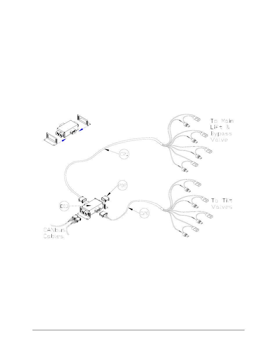
8.3 Input Module
1. Install the input module (E03) on the boom near the sprayer valve block. Secure it to the
boom using cable ties or optional brackets.
2. Connect the free end of the CANbus cable (C02) from the valve module to the input
module.
3. Insert the 12 pin plug (P02) into the OEM 3 connector on the end of the input module.
4. Connect the 12 pin connector on the tilt interface cable (C20) to the Thru 2 connector on
the side of the input module. Insert the other connectors on C20 into the tilt connectors
on the sprayer valve block.
Figure 19: Input Module Connections
5. Connect the 12 pin connector on the main lift interface cable (C21) to the Thru 1
connector on the side of the input module.
6. Insert the “Aux 2” tee between the directional cartridge and the existing cable.
7. Insert the “Main Up” tee between the “Main” function cartridge and the existing cable.
8. Connect the unused male and female connectors on “Main Down” to each other
9. If the sprayer has a bypass valve, insert the 2-pin tee connector marked “AUX 1” into the
bypass valve connection. If the sprayer does not have a bypass valve, connect the plug and
receptacle “Aux 1” connectors together.