3 input module – NORAC UC5-BC-JD11 User Manual
Page 26
23
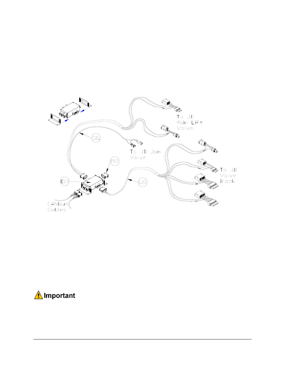
8.3 Input Module
1. Install the input module (E03) on the boom near the John Deere valve block. Secure it to
the boom using cable ties or optional brackets.
2. Connect the CANbus cable (C02) from the valve module to the input module. Connect
cable C03 to the other CANbus connector and route to the 8-way coupler.
3. Insert the 12 pin plug (P02) into the OEM 3 connector on the end of the input module.
Figure 25: Input Module Connections
4. Connect the 12 pin connector on the tilt interface cable (C20) to the Thru 2 connector on
the side of the input module. Insert the other 4-pin and 6-pin connectors on C20 into the
tilt connectors on the John Deere solenoids.
5. Connect the 12 pin connector on the main lift interface cable (C21) to the Thru 1
connector on the side of the input module. Insert the 4-pin connectors on C21 into the
main lift connectors on the John Deere solenoids. The 2-pin Deutsch connectors on cable
C21 are not used for this installation; connect the male and female 2-pin connectors
together and coil the cables where they will not interfere with any moving parts.
There is one set of different connectors included with the tilt interface cable.
Some John Deere sprayers use this connector on the left down function. If the
sprayer has this connector, remove the existing connectors using the included pin
removal tool. Insert the wires into the new connector and ensure they are in the
same position as they were in the previous connector.