NORAC UC4+BC+HD3 Part 2 User Manual
Page 5
2. Connect the power cable (C10) to the
UC4+ Control Panel in the sprayer cab.
Ensure that both plugs (P16A and P4) are
connected to the panel (Figure 2).
Ensure that the UC4+ Control Panel
is OFF for the remaining installation
(Bottom of switch pressed IN). Use
caution when handling the 12V
power line of the sprayer wiring.
3. Connect the 3-pin AMP connector (P3) on
the C10 cable to an auxiliary power
connection inside the sprayer cab. If an
appropriate connector(s) cannot be found it
may be necessary to cut off the connector(s)
and splice into the existing wiring.
4. Route the free end (R16) of C10 to the
exterior of the cab, to the vicinity of the
tractor hitch. This connector will provide
your hitch connection. Route the cable
accordingly and connect it to P16 on the
sprayer. The procedure for the installation
of the UC4+ system is now complete.
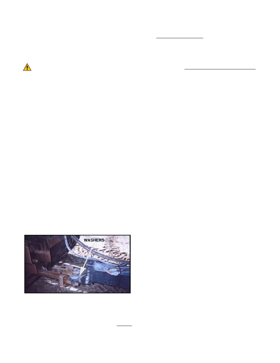
5. For optimal performance of the UC4
system, there should be very little play at the
hitch clevis. The addition of polymer
washers can help tighten up this connection
(Figure 3).
Figure 3: Hitch Point
6. Power on the UC4+ panel, if “HD3” shows
up as your sprayer type, you can start the
ReTune process as per the UC4+
Operator Manual. This will tune the
UC4+ hydraulic parameters to your tractor
hydraulic system.
7. If no type is selected yet, start the Install as
per the UC4+ Operator Manual.