7 electrical installation – NORAC UC4.5-BC-FC2 User Manual
Page 18
15
7 Electrical Installation
1. Install the UC4.5 Control Panel (E01) in the cab of the sprayer. Mount the panel where it
will be clearly visible and within easy reach of the operator.
A good spot to mount the UC4.5 control panel is on the right hand side of the cab to the
Roll Over Protection Bar. Four pilot holes for the screws provided need to be drilled to
facilitate the control panel mounting.
Another option is to purchase an adapter for the flexible panel mount that has a 3/8" NC
threaded stud on the end to bolt through an existing mount. These can be found at your
local outdoor store as a RAM mount part number RAM-B-236. (See
http://www.ram-
mount.com/
)
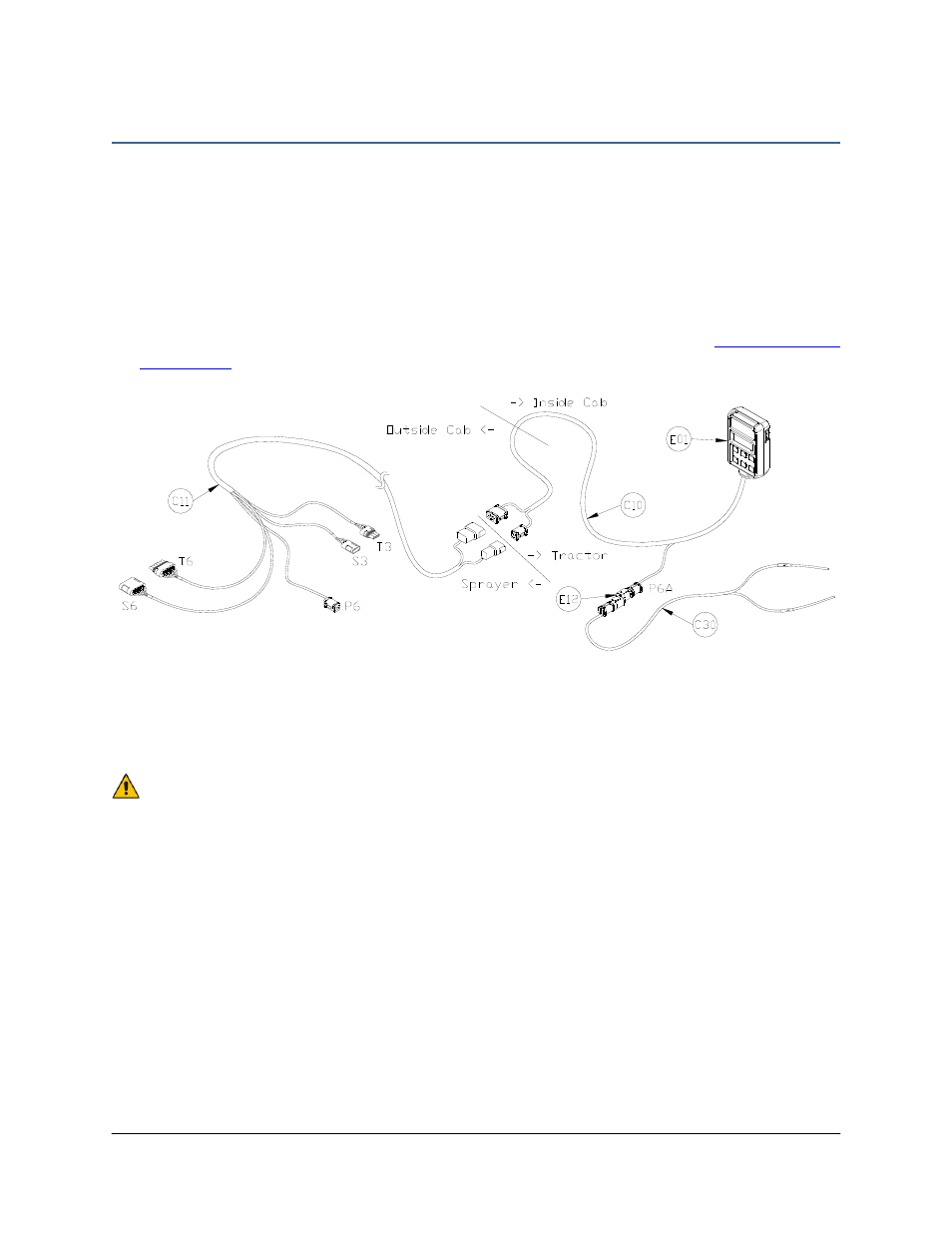
Figure 15: Cable Configurations: C10, C11 and C30
2. Connect the UC4.5 power cable (C10) to the UC4.5 control panel in the sprayer cab.
Ensure both plugs (P16 and P4) are connected to the panel. Cable tie C10 to the RAM
mount to help provide strain relief.
Ensure the UC4.5 control panel’s power is OFF for the remaining installation
(Bottom of switch pressed IN).
3. Connect the power cable connector (P6A) to C30 using a 2-way coupler (E12). Connect
C30 to an appropriate power supply.
4. Route the P12/P6B of C10 out of the cab.
5. Connect the P12/P6B from C10 to R12/R6 of C11 at the hitch. This connection is the hitch
disconnect.
6. Route C11 to the vicinity of the valve block at the rear of the sprayer.
7. Connect the 6-pin shroud (S6) on C12 to the 6-pin tower (T6) on C11. Route the free end
of C12 to the existing valve block.