3 hydraulic plumbing – NORAC UC4.5-BC-CS3 User Manual
Page 25
22
8.3 Hydraulic Plumbing
From this point on in the installation the booms will be inoperative until the
hydraulics are fully installed.
1. After the NORAC valves are mounted, the hydraulic hoses and fittings can be plumbed. The
plumbing for the hydraulic circuit is shown schematically in Figure 3.
2. Attach the four 6FORXR-6MOR tee fittings (F03) to the 90 degree fittings on the NORAC
block.
3. Connect the “lower” line (“A” line) hoses from the cylinders to one end of the 6FORXR-
6MORT tee fitting (F03) on the NORAC “A” ports.
4. Connect the “raise” line (“B” line) hoses from the cylinders to one end of the 6FORXR-
6MORT tee fitting (F03) on the NORAC “B” ports.
5. Install the four supplied hoses (H01) between the tee fitting (F03) and the Case valve block.
Use the 6MB-6MOR adapter (F05) to connect the hose to the Case valve block.
6. Tee the pressure and tank lines (H02) for the NORAC valve block into the existing P and T
lines on the Case sprayer block. Use the 8FORXR-8MORT (F06) fittings and the 8MOR-
8MB (F04) adapters.
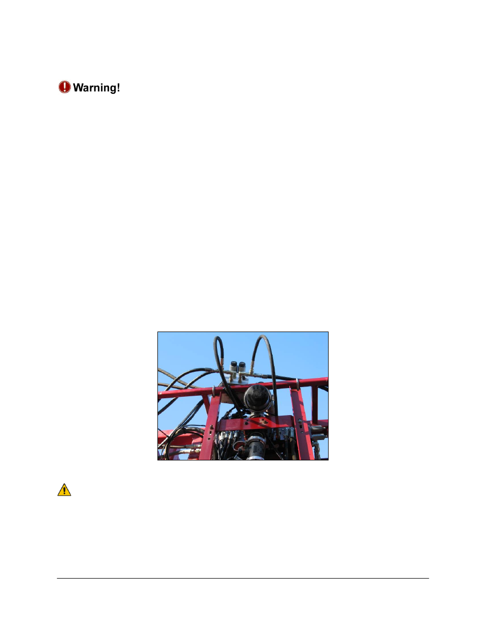
Figure 22: Hydraulic Plumbing Example
Use the supplied hoses H03 and H04 if the existing lines are too short to reach
the block.