3 hydraulic plumbing – NORAC UC4.5-BC-CS2 User Manual
Page 25
22
8.3 Hydraulic Plumbing
From this point on in the installation the booms will be inoperative until the
hydraulics are fully installed.
1. After the NORAC valves are mounted, the hydraulic hoses and fittings can be plumbed. The
plumbing for the hydraulic circuit is shown schematically in Figure 3.
2. Remove the existing fittings from the sprayer valve block and plug the “A” and “B” ports
with the 4FJCN plugs (F04).
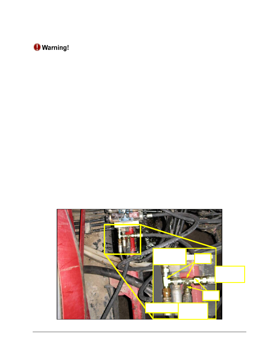
3. The “A” ports of the cylinders must be teed in to the tank (“T”) lines. Install two 6FJXR-
6MJT Tee fittings (F06) into the “T” port of the NORAC block as shown in Figure 3 and
Figure 22.
4. Connect the “A”-line hoses from the cylinders to F06 with 6FJ-4MJ fittings (F03).
5. The “raise” lines from the side of the cylinders, which raise the booms, must be connected
to the “B” ports of the NORAC valve block. Use 6FJ-4MJ fittings (F03) between the existing
hoses and NORAC valve block.
6. Install the provided hoses (H02) to pressure (“P”) and tank (“T”) ports of the NORAC
valve block.
7. Connect the other ends of H02 to pressure (“P”) and tank (“T”) ports of the sprayer valve
block with the 6MJ-6FJX90 fittings (F02) and the 6MB-6MJ couplings (F05).
Figure 22: Tank Port Hydraulic Plumbing
NORAC
Tank Port
Cylinder
A Line
Cylinder
A Line
Tank Line
F06
F03