MUTEC MC-2 User Manual
Page 18
\\\\\\\\\\\\
AP P E N D I X
AP P E N D I X
AP P E N D I X
> > > > > > > > > > > > > > > > > > > > > > > > > > > > > > > > > > > > > > > > > > > > > > > > > > > > > > > > > > > > > > > > > > > >
> > > > > > > > > > > > > > > > > > > > > > > > > > > > > > > > > > > > > > > > > > > > > > > > > > > > > > > > > > > > > > > > > > > >
88
Manual SDs-01 E 3.2.2003 18:26 Uhr Seite 14
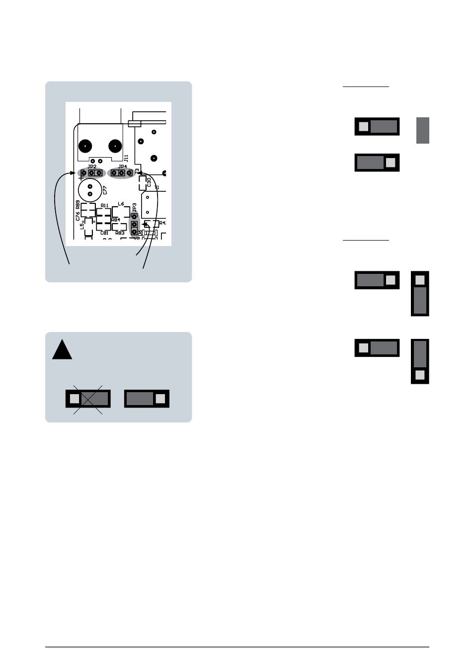
Connecting the AES/EBU ID Input to Ground
When MC-2 is shipped, the BNC-based
AES/EBU ID input is isolated from ground.
Setting the jumper one pin forward in direction
to the housing’s leftside (viewed from the front
panel) will connect the BNC input connector to
ground.
This setting is also necessary when switching-off
the termination (see below)!
Jumper:
JP 3
JP 2
CAUTION! Disconnect the unit from the mains before opening!
Remount the aluminium cover thoroughly before you attempt to operate
the unit!
Switching-off the Termination of the AES/EBU ID Input
CAUTION! Disconnect the unit from the mains before opening!
Remount the aluminium cover thoroughly before you attempt to operate
the unit!
JP 2
When MC-2 is shipped, the BNC-based
AES/EBU ID input is terminated internally with
75
Ω. Therefore, two jumpers are put on two
3-pin sockets, JP 4 for termination and JP 3 for
status.
JP 4
Moving the jumpers of each socket in the
opposite position will switch of the 75
Ω ter-
mi-nation of the AES/EBU ID input.
JP 3
JP 4
When moving the jumpers of the
sockets JP 3 and JP 4 to switch-off
the AES/EBU ID input termination,
the input hast to be connected to ground
simultaneously!
!
JP 2
JP 2
wrong
right
AES/EBU ID
INPUT
AES/EBU
INPUT
Termination connector JP 4
Status connector JP 3
Ground connector JP 2