Appendix, Pin assignment of the connectors, Technical data – MUTEC MC-1.2 User Manual
Page 18
18
Appendix
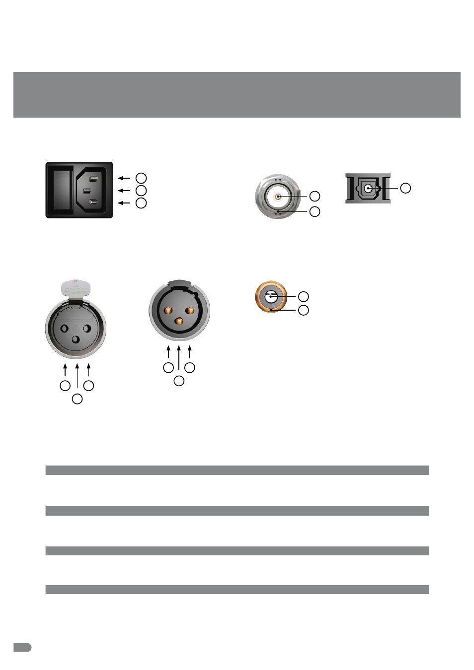
Pin Assignment of the Connectors
Mains
1
1 Live, phase (brown; USA: black)
2 Protective earth (green/yellow; USA: green)
3 Neutral (blue; USA: white)
2
3
2
3
1
1 Audio ground
2 a conductor (hot / +)
AES/EBU, XLR, Input
for AES3
RCA, Input/Output
for S/P-DIF
1 Audio signal
2 Audio ground
1
2
1
3
2
1 Ground
2 a conductor (hot / +)
AES/EBU, XLR, Output
for AES3
NOTE:
The RCA-based S/P-DIF
inputs and outputs are
not galvanically isolated,
due to
IEC 60958.
Optical TOSLINK Input/Output
for S/P-DIF
1
1 Optical signal
BNC Input/Output for
AES3id, S/P-DIF
1 Signal
2 Ground
1
2
USB Input & Output
Interface
1 x USB-B connector
Formats & Resolutions
Type 1 formats: PCM 16 bit, PCM 24 bit, PCM 32 bit, FLOAT 32 bit for USB 1.0 & USB 2.0
Supported Sampling Rates
USB 1.0: 44.1 kHz & 48.0 kHz, USB 2.0: 44.1 kHz to 192.0 kHz
AES3 Audio Input
Interface
1 x XLR female, transformer balanced, input impedance 110 Ω, 200 mV–7.0 V
Format, Resolution
AES3-1992/2003, AES11-1997/2003, IEC 60958, 16–24 bits
Supported Sampling Rates
32.0 kHz to 192.0 kHz
S/P-DIF Optical Audio Input (OP)
Interface
1 x Toslink
TM
, EIAJ RC-5720
Format, Resolution
IEC 60958, 16–24 bits
Supported Sampling Rates
32.0 kHz to 192.0 kHz
S/P-DIF RCA Audio Input (CO)
Interface
1 x Coaxial (RCA female), unbalanced, 0.5 –1.0 Vpp @ 75 Ω, output impedance 75 Ω
Format, Resolution
IEC 60958, 16–24 bits
Supported Sampling Rates
32.0 kHz to 192.0 kHz
Technical Data