Milwaukee Tool 8988-20 User Manual
Page 3
4
5
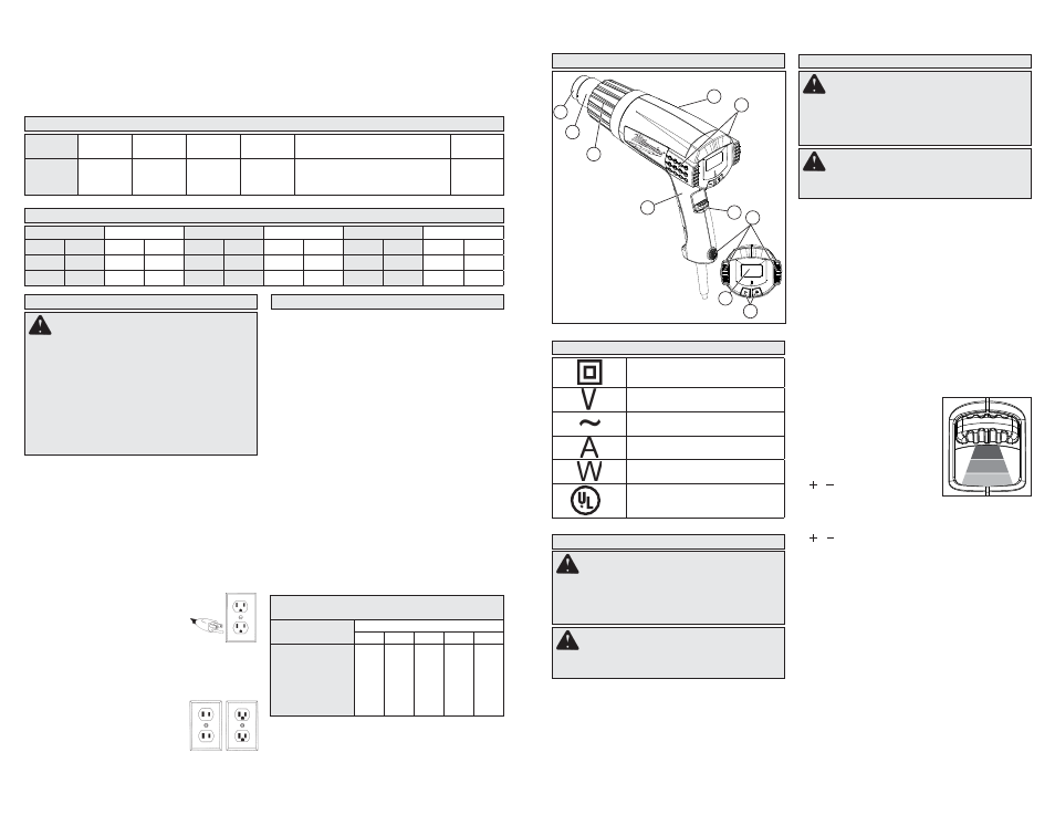
1. Accessory
attachment
area
2. Nozzle
3. Front cover
4. Nameplate (on back)
5. Intake vents
6. Handle
7. ON/OFF/Airfl ow switch
8. Support stand bumpers
9. LCD
10. Temperature controls
Grounded Tools: Tools with Three Prong Plugs
Tools marked “Grounding Required” have a three wire
cord and three prong grounding plug. The plug must be
connected to a properly grounded outlet (See Figure
A). If the tool should electrically malfunction or break
down, grounding provides a low resistance path to
carry electricity away from the user, reducing the risk
of electric shock.
The grounding prong in the plug is connected through
the green wire inside the cord to the grounding system
in the tool. The green wire in the cord must be the only
wire connected to the tool's grounding system and
must never be attached to an electrically “live” terminal.
Your tool must be plugged into an appropriate
outlet, properly installed and grounded in accor-
dance with all codes and ordinances.
The plug and outlet should look like
those in Figure A.
Double Insulated Tools: Tools with Two Prong Plugs
Tools marked “Double Insulated” do not require
grounding. They have a special double insulation
system which satisfi es OSHA requirements and com-
plies with the applicable standards of
Underwriters Laboratories, Inc., the
Canadian Standard Association and
the National Electrical Code. Double
Insulated tools may be used in ei-
ther of the 120 volt outlets shown in
Figures B and C.
Grounded tools require a three wire extension cord.
Double insulated tools can use either a two or three wire
extension cord. As the distance from the supply outlet
increases, you must use a heavier gauge extension
cord. Using extension cords with inadequately sized
wire causes a serious drop in voltage, resulting in loss
of power and possible tool damage. Refer to the table
shown to determine the required minimum wire size.
The smaller the gauge number of the wire, the greater
the capacity of the cord. For example, a 14 gauge cord
can carry a higher current than a 16 gauge cord. When
using more than one extension cord to make up the total
length, be sure each cord contains at least the minimum
wire size required. If you are using one extension cord for
more than one tool, add the nameplate amperes and use
the sum to determine the required minimum wire size.
Guidelines for Using Extension Cords
• If you are using an extension cord outdoors, be sure
it is marked with the suffi x “W-A” (“W” in Canada) to
indicate that it is acceptable for outdoor use.
• Be sure your extension cord is properly wired and in
good electrical condition. Always replace a damaged
extension cord or have it repaired by a qualifi ed person
before using it.
• Protect your extension cords from sharp objects,
excessive heat and damp or wet areas.
each work session, place paint scrapings in a double
plastic bag, close it with tape or twist ties and dispose.
• Remove protective clothing and work shoes
in the work area to avoid transferring dust to
Fig. B
Fig. C
GROUNDING
SPECIFICATIONS
* Cubic feet per minute
Cat. No.
Volts AC
Max.
Amps
Max.
Watts
Switch
Setting
Temperature
Airfl ow
CFM*
8988-20
120
12.5
1500
I
II
III
120°F (49°C)
120°F - 1150°F (49°C - 621°C)
120°F - 1150°F (49°C - 621°C)
3.6
10.6
17.6
READ AND SAVE ALL
INSTRUCTIONS FOR FUTURE USE.
* Based on limiting the line voltage drop to fi ve volts
at 150% of the rated amperes.
EXTENSION CORDS
FUNCTIONAL DESCRIPTION
SYMBOLOGY
Double Insulated
Volts
Alternating Current
Amps
Watts
C
US
Underwriters Laboratories, Inc.
United States and Canada
other parts of the building. Wash work clothes
separately. Wipe shoes off with a wet rag that is then
washed with the work clothes. Wash hair and body
thoroughly with soap and water.
SAVE THESE INSTRUCTIONS
ASSEMBLY
Installing/Removing Nozzles
1. To install, slide the nozzle onto the heat gun
nose.
2. Adjust heat, airfl ow, distance and length of ap-
plication as necessary.
3. To remove, allow tool to cool to room tempera-
ture, then pull nozzle away from tool.
OPERATION
Selecting Temperature
The proper amount of heat for each application
depends on the temperature selected, distance
between the nozzle and workpiece, and the length
of time heat is applied. Experiment with scrap ma-
terials and start with the lowest temperature. Be
cautious when working until the proper combination
of heat, distance and time of application has been
obtained. Use a back and forth motion when ap-
plying heat unless concentrated heat is desirable.
When done, allow the nozzle to cool by placing the
tool upright on a fl at surface using the support stand
areas. Place the cord so the heat gun won’t tip.
The electronic temperature control system
regulates the temperature within the tool's heat-
ing element. Unlike non-electronic heat guns,
MILWAUKEE's electronic heat gun will maintain
the temperature.
1. For Low Airfl ow/Low Tem-
perature, push the switch to
the (I) position.
2. For Medium Airflow/Vari-
able Temperature, push
the switch to the (II) posi-
tion. Use the temperature
/ buttons to increase or
decrease the temperature
(100°F - 1100°F) by 10°F increments.
3. For High Airfl ow/Variable Temperature, push the
switch to the (III) position. Use the temperature
/ buttons to increase or decrease the tem-
perature (100°F - 1100°F) by 10°F increments.
When the tool is switched OFF, the last selected
temperature is retained.
Hands-Free Use
The heat guns can be positioned upright on a stable
surface, leaving both hands free for the application.
Always place the tool upright on a fl at surface using
the support stand areas. Place the cord so the heat
gun won’t tip. The rear vent openings are designed
to allow air fl ow even when the tool is resting on
the end cap. Do not cover the vents with foreign
materials such as clothing or rags.
Types of Nozzles
• Hook Nozzle - Surrounding heat for thin pipe weld-
ing, soft soldering copper pipes, tube shaping and
shrinking of shrink tubes.
• Air Reduction Nozzle - Intensifi ed, spot directed
heat for corners, plexiglas bending and soldering.
WARNING
Improperly connecting the
grounding wire can result in the risk of electric
shock. Check with a qualifi ed electrician if you
are in doubt as to whether the outlet is properly
grounded. Do not modify the plug provided with
the tool. Never remove the grounding prong
from the plug. Do not use the tool if the cord or
plug is damaged. If damaged, have it repaired
by a MILWAUKEE service facility before use.
If the plug will not fi t the outlet, have a proper
outlet installed by a qualifi ed electrician.
WARNING
To reduce the risk of injury,
do not remove or attach accessory tips until
tool has cooled to room temperature.
WARNING
To reduce the risk of injury,
always unplug tool before attaching or remov-
ing accessories or making adjustments. Use
only specifi cally recommended accessories.
Others may be hazardous.
WARNING
To reduce the risk of injury,
wear safety goggles or glasses with side
shields.
WARNING
To reduce the risk of injury,
always unplug tool before attaching or remov-
ing accessories or making adjustments. Use
only specifi cally recommended accessories.
Others may be hazardous.
Fig. A
8
2
1
3
6
7
5
4
10
9
Recommended Minimum Wire Gauge
For Extension Cords*
Nameplate Amps
Extension Cord Length
25'
50'
75'
100'
150'
0 - 2.0
2.1 - 3.4
3.5 - 5.0
5.1 - 7.0
7.1 - 12.0
12.1 - 16.0
16.1 - 20.0
18
18
18
18
16
14
12
18
18
18
16
14
12
10
18
18
16
14
12
10
--
18
16
14
12
10
--
--
16
14
12
12
--
--
--
I
II
III
TEMPERATURE CONVERSIONS
°C = °F
°C = °F
°C = °F
°C = °F
°C = °F
°C = °F
38
100
149
300
260
500
371
700
482
900
593
1100
93
200
200
392
300
572
400
752
500
932
600
1112
100
212
204
400
316
600
427
800
538
1000
649
1200