Milwaukee Tool 2680-22 User Manual
Page 4
6
7
Cat. No.
Volts
DC
No Load
RPM
Spindle
Thread Size
Wheel
Size
2680-20
18
9000
5/8"-11
4-1/2"
FUNCTIONAL DESCRIPTION
SYMBOLOGY
SPECIFICATIONS
ASSEMBLY
WARNING
Recharge only with the
charger specifi ed for the battery. For specifi c
charging instructions, read the operator’s
manual supplied with your charger and battery.
Inserting/Removing the Battery
To remove the battery, push in the release buttons
and pull the battery pack away from the tool.
To insert the battery, slide the pack into the body of
the tool. Make sure it latches securely into place.
1. Side handle
2. Spindle lock
3. Side handle sockets
4. Paddle switch
1
4
5
6
7
3
2
5. Switch lock-off
6. Guard
7. Guard lock lever
Installing Side Handle
The side handle may be installed on either side
or the top of gear case. Position side handle in
the location which offers best control and guard
protection. To install, thread side handle into side
handle socket and tighten securely.
Installing, Removing and Adjusting the Guard
This tool is shipped with a guard. A guard must be
used when using the tool as a grinder. The guard
may be removed when using tool as a sander.
1. To remove the guard, remove the battery pack
and remove any accessories from spindle.
2. Press in the lock lever and rotate the guard to
line up the tabs on the grinder with the slots in
the guard.
3. Press in the lock lever and lift the guard straight
up and away from the tool.
4. To install the guard, remove the battery pack
and remove any accessories from the spindle.
5. Line up the tabs on the grinder with the slots in
the guard.
6. Press in the lock lever and press the guard onto
the tool.
7. To adjust the guard, press in the lock lever and
rotate the guard to one of fi ve detent slots.
WARNING
To reduce the risk of injury
when grinding:
• ALWAYS use the proper guard.
• ALWAYS properly install the guard.
• ALWAYS hold the tool fi rmly with both
hands using the handles provided before
and during grinding.
• NEVER use a wheel that has been dropped.
• NEVER bang grinding disc onto work.
• NEVER grind without proper safety
equipment.
Tab
slots
Fig. 1
Detent
slots
WARNING
Always remove battery
pack before changing or removing accesso-
ries. Only use accessories specifi cally recom-
mended for this tool. Others may be hazardous.
Installing/Removing Accessories
Make sure the wheel does not extend beyond the
bottom of the guard. Threaded hub grinding wheels
may require a deeper guard (see "Accessories").
1. Remove the battery pack.
2. Properly position the guard (Fig. 2).
WARNING
Only use accessories with
Maximum Safe Operating Speed rated at least
equal to the maximum speed marked on the
power tool. This speed is based on the strength
of the wheel, allowing for a reasonable mea-
sure of safety. It is not meant to imply a best or
most effi cient operating speed. Do not exceed
the Maximum Safe Operating Speed.
Controlled Start
The controlled start feature reduces the torque
reaction "jerk" when its trigger is pulled.
Paddle Switch Operation
To start the tool, grasp the handle and side handle
fi rmly. Pull the lock-off button back and squeeze
the paddle switch.
To stop the tool, release the paddle switch. Make
sure the tool comes to a complete stop before lay-
ing the tool down.
General Operation
1. If you have just installed an accessory or are
beginning a period of work, test it by letting it
spin for one minute before applying it to the
workpiece. Out-of-balance or damaged acces-
sories can mar workpiece, damage the tool, and
cause stress that may cause accessory failure.
2. Use a clamp, vise or other practical means to
hold your work, freeing both hands to control
the tool.
3. Hold tool securely with both hands.
4. Start the tool.
5. Allow accessory to come to full speed before
beginning work.
6. Control pressure and surface contact between
accessory and workpiece. Too much pressure
slows speed.
If the tool stalls, release the trigger to reset.
Lighten pressure to avoid stalling.
7. When fi nished, turn off the tool and make sure
it comes to a complete stop before laying it
down.
OPERATION
WARNING
Always remove battery
pack before changing or removing acces-
sories. Only use accessories specifically
recommended for this tool. Others may be
hazardous.
WARNING
To reduce the risk of injury,
wear safety goggles or glasses with side shields.
5. Place the selected wheel on the spindle and align
it with the fl ange.
6. Position the fl ange nut over the spindle according
to wheel thickness (Fig. 4).
7. Press in the spindle lock button while turning the
fl ange nut clockwise. Tighten securely using a
spanner wrench.
8. To remove wheel, remove the battery pack and
reverse the procedure.
Flange nut
position for
1/8" thick or less wheels
Fig. 4
1/8"
1/4"
Flange nut
position for
1/4" thick or more wheels
Fig. 2
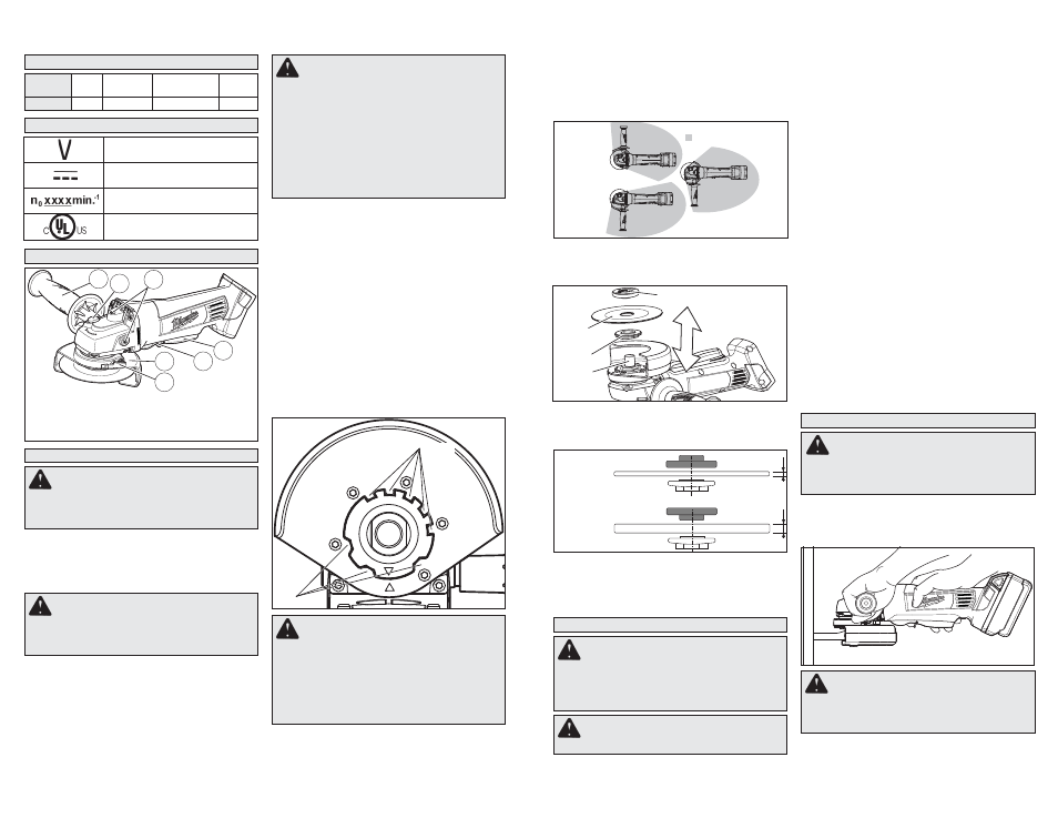
Operator's Zones
Spindle
Flange
Wheel
Flange nut
Fig. 3
3. Wipe the flange, flange nut and spindle to
remove dust and debris. Inspect the parts for
damage. Replace if needed.
4. Place the fl ange on spindle, as shown.
Fig. 6
WARNING
A Type "1" guard must be
installed when using a cut-off wheel to provide
maximum protection for the operator if the
wheel should break.
WARNING
Using the face of a Cut-Off
Wheel (as in grinding) will cause the Wheel
to crack and break, resulting in serious per-
sonal injury.
USING CUT-OFF WHEELS
Type "1" Cut-Off Wheels are suited for small cut-off
and shallow notching operations only.
When using a cut-off wheel, hold the tool as shown,
using only the edge of the wheel.
Volts
Direct Current
No Load Revolutions per
Minute (RPM)
Underwriters Laboratories, Inc.
United States and Canada