Telephone bypass module, Quick start guide entraguard bronze – Keri Systems EntraGuard Bronze Bypass Switch Module User Manual
Page 2
Telephone Bypass Module
1530 Old Oakland Road, Suite 100
01927-001 Rev. A
San Jose, CA 95112 USA
(800) 260-5265 (408) 451-2520 FAX (408) 441-0309
Web: http://www.kerisys.com E-mail: [email protected]
Page 2 of 2
Quick Start Guide
EntraGuard Bronze
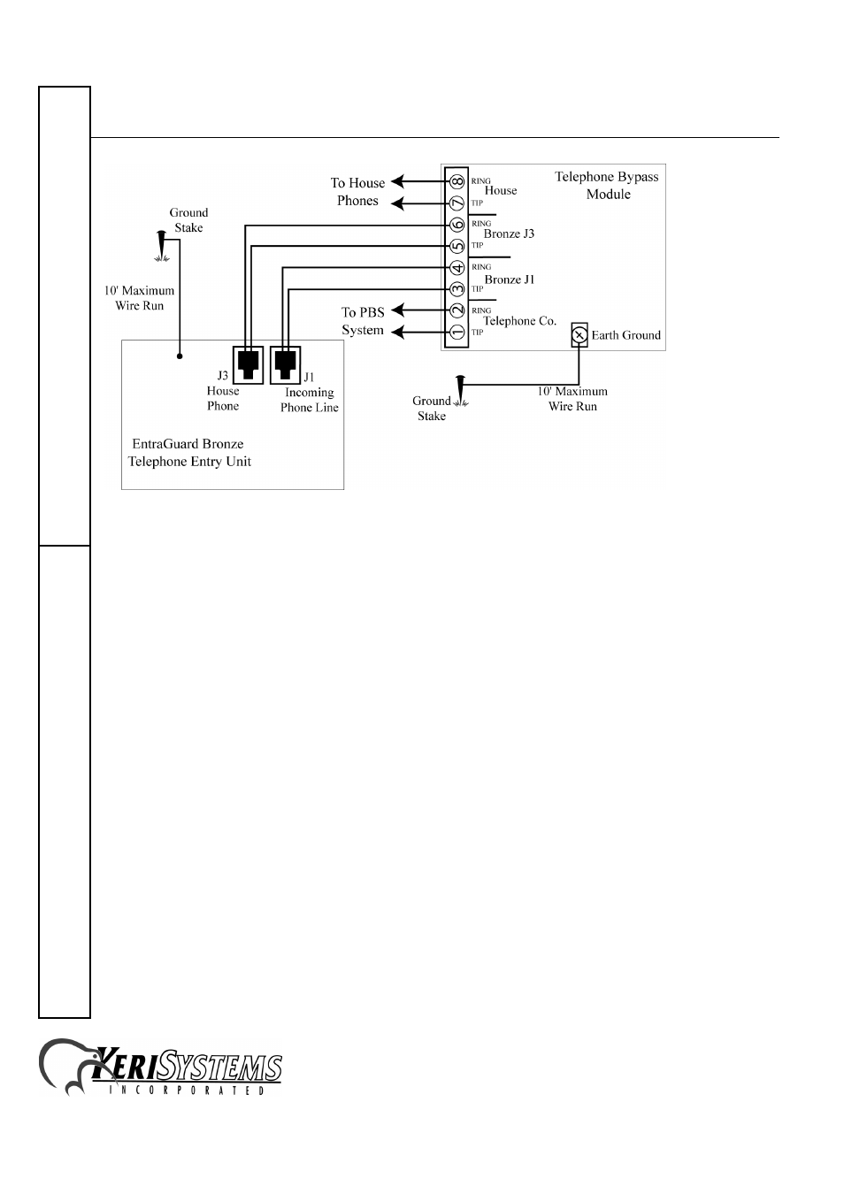
Figure 2: Bronze Telephone Bypass Module
1. Connect the bypass module’s EARTH GROUND terminal to a good earth ground.
2. Before connecting the incoming telephone line to the bypass module, check the polarity of the
wires with a DC voltmeter. Connect the negative wire (RING - usually green) to the bypass
module TELCO RING terminal. Connect the positive wire (TIP - usually red) to the bypass
module TELCO TIP terminal.
3. Connect the resident’s local telephone line RING (usually green) to the bypass module HOUSE
RING. Connect the local telephone line TIP (usually red) to the bypass module HOUSE TIP
terminal.
4. Connect the Bronze Incoming Phone Line RING (J1) to the bypass module RE-1 TELCO RING
terminal. Connect the Bronze Incoming Phone Line TIP (J1) to the bypass module RE-1
TELCO TIP terminal.
5. Connect the Bronze House Phone RING (J3) to the bypass module RE-1 HOUSE RING
terminal. Connect the Bronze House Phone TIP (J3) to the bypass module RE-1 HOUSE TIP
terminal.