Crestron electronic IM-RXV1-M User Manual
Page 14
iMedia Receiver with Video & Mic Input Crestron IM-RXV1-M & IM-RXV3-M
Connectors, Controls & Indicators (Continued)
#
CONNECTORS
1
, CONTROLS
& INDICATORS
DESCRIPTION
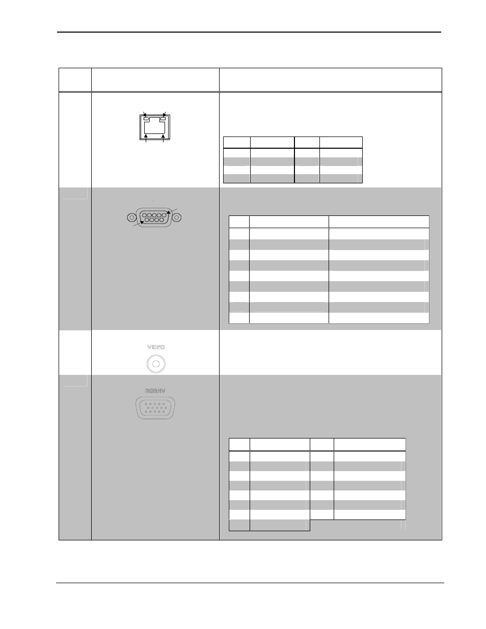
12
LAN
3
GREEN
LED
YELLOW
LED
PIN 8
PIN 1
(1) 8-wire RJ-45 with two LED indicators;
10BaseT/100BaseTX Ethernet port;
Green LED indicates link status;
Yellow LED indicates Ethernet activity.
PIN
SIGNAL
PIN
SIGNAL
1
TX +
5
N/C
2
TX -
6
RC -
3
RC+
7
N/C
4
N/C
8
N/C
13
COM
COM
Pin 1
Pin 9
(1) DB9 male, bidirectional RS-232 port; Up to 115.2k baud;
hardware and software handshaking support.
PIN
DIRECTION
DESCRIPTION
1
To IM-RXV1/3-M
(DCD) Data Carrier Detect
2
To IM-RXV1/3-M
(RXD) Receive Data
3
From IM-RXV1/3-M
(TXD) Transmit Data
4
From IM-RXV1/3-M
(DTR) Data Terminal Ready
5
Common
(GND) Ground
6
From IM-RXV1/3-M
(DSR) Data Set Ready
7
From IM-RXV1/3-M
(RTS) Request To Send
8
To IM-RXV1/3-M
(CTS) Clear To Send
9
To IM-RXV1/3-M
(RI) Ring Indicator
14 VIDEO
(1) RCA female, composite video output;
Output impedance: 75 ohms;
Output level: 1 V
p-p
nominal.
15
RGBHV
1
5
6
10
11
15
(1) DB15HD, female, RGB output; displays RGB signal from RGB
source connected to IM transmitter;
Formats: RGBHV, RGBS, RG
S
B;
Output impedance: 75 ohms;
Sync impedance: 100 ohms;
Maximum output level: 1 V
p-p
maximum;
Sync level: 5 V
p-p
.
PIN
FUNCTION
PIN
FUNCTION
1
Red Video
9
No Connect
2
Green Video
10
Ground
3
Blue Video
11
No Connect
4
Reserved
12
Monitor Sense 1
5
Ground
13
Horizontal Sync
6
Red Ground
14
Vertical Sync
7
Green Ground
15
Monitor Sense 2
8
Blue Ground
(Continued on following page)
10
• iMedia Receiver: IM-RXV1-M & IM-RXV3-M
Operations & Installation Guide – DOC. 6593A