ISP Technologies BASS VECTOR 115 User Manual
Page 4
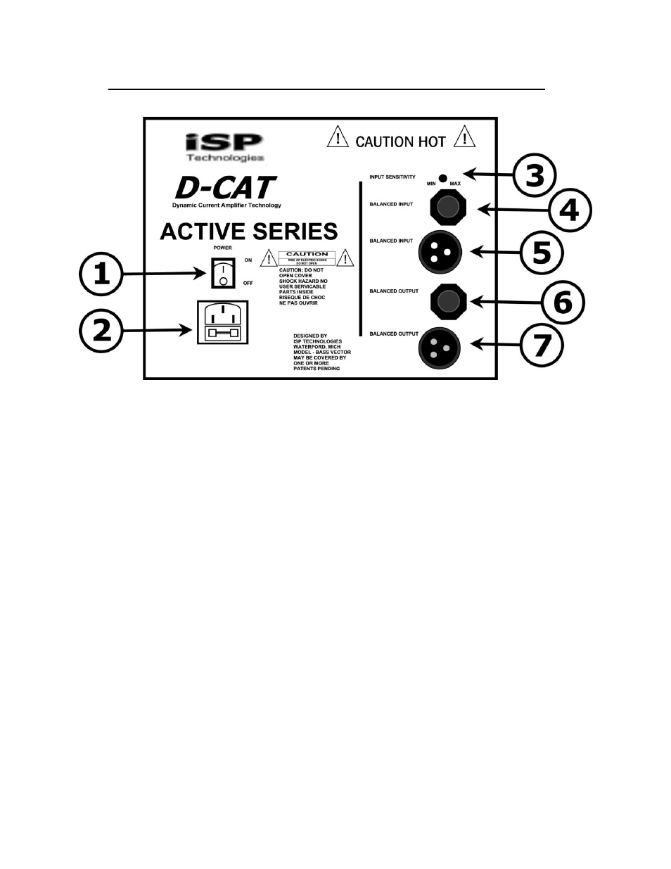
BASS VECTOR 115 CABINET BACK PANEL CONNECTIONS
1. POWER JACK
This switch controls the power to the amp module. This switch has only two positions
up is on and down is off.
2. POWER INLET MODULE
This module provides a connection for the power cord and also houses the main fuse.
(See the fuse replacement section)
3. INPUT SENSITIVITY
This control determines the overall input level of the signal to the power amp of the
bass vector. This will not affect the level of the signal passing through the output
connectors.
4. BALANCED ¼ INPUT
This jack provides an input for balanced or unbalanced line level signal source.
5. BALANCED XLR INPUT
This female connector provides an input for balanced line level signal source.
6. BALANCED ¼ OUTPUT
This jack provides a balanced loop through for connecting to additional powered
cabinets.
7. BALANCED XLR OUTPUT
This male connecter provides a balanced loop through for connecting to additional
powered cabinets.