Front panel understanding the theta amplifier, Theta preamp1 – ISP Technologies THETA Head User Manual
Page 3
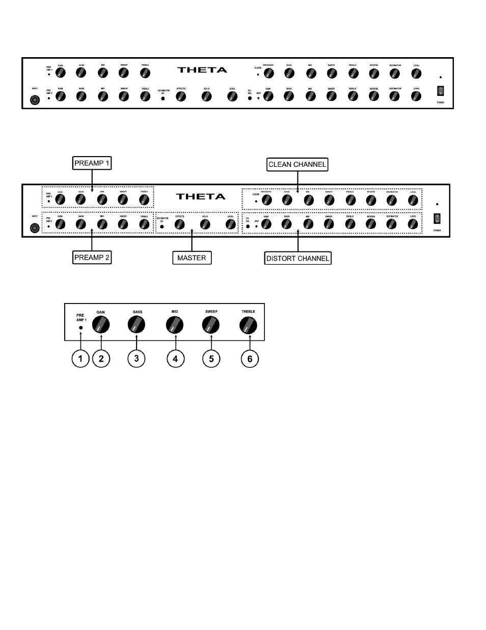
FRONT PANEL
Understanding the THETA amplifier
6. POWER SWITCH
Switches the unit on and off.
7. POWER LED
THETA PREAMP1
1. PREAMP1 ON LED
This led indicates when PREAMP1 is active and in the signal path. NOTE: The
PREAMP1 switch on the THETA FOOTCONTROLLER switches PREAMP1 on and off.
PREAMP1 is functional only when the CLEAN channel is selected. PREAMP1 and
PREAMP2 will automatically switch with the channel selected.
2. PREAMP1 GAIN CONTROL
This control adjusts the amount of gain in the signal path of PREAMP1.
3. BASS
This control adjusts the amount of boost or cut in the low frequency portion of the
spectrum of PREAMP1. The available BASS boost and cut range is +/-15 decibels.
4. MIDRANGE BOOST/CUT CONTROL
This control works in conjunction with the SWEEP frequency control 5. The MID and
SWEEP controls work together to provide a semi-parametric tone control. When the
MID control is set at 12:00 straight up there is no boost or cut in the MID frequency
portion of the spectrum. The graph below shows the response of the MID boost/cut
and SWEEP controls. The MID control allows +/- 12db of boost or cut to be applied
at the frequency determined by the SWEEP control.