Setting ra8 dip switches, Final word – Haltech RA8 User Manual
Page 2
2
Setting RA8 DIP Switches
The DIP switches must be configured to suit the application. Access to the DIP switches
is achieved by removing the back plate of the extrusion (opposite side to the connector).
Of the 8 switches, the first 4 are for channel A, and the last 4 for channel B. The switches
are arranged so that switch 1 does the same for channel A as switch 5 does for channel B,
this is repeated for switches 2 and 6, 3 and 7, and 4 and 8. Each channel will have
identical settings if the switch settings are copied to the other channel.
The settings are summarized below:
Channel A
1.
This switch is used to disable the RA8 to piggyback to an existing reluctor
connected to another ECU if the reluctor negative is biased to a voltage
other than 0V (Ground). It is recommended that this switch be ON to
disable this feature unless it is found that the existing ECU biases the coil
negative to a voltage other than 0V relative to battery ground. In this case,
the switch will decouple the RA8 from the ECU biasing so that it can
process the signal without affecting the existing ECU.
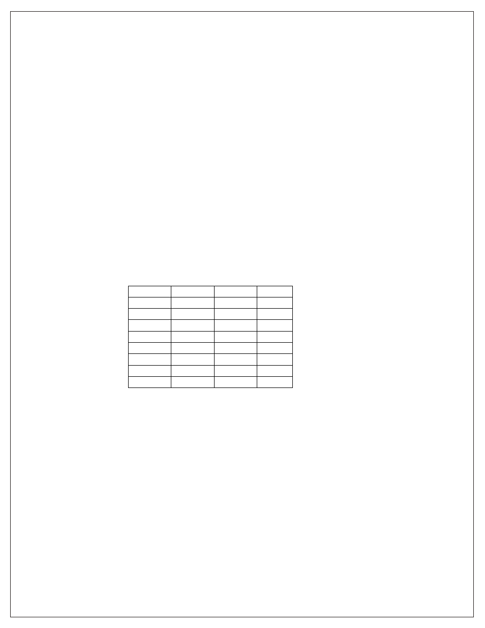
2,3,4.
These switches set the gain as presented in the table below:
Switch 2 Switch 3 Switch 4 Gain
Off
Off
Off
1
On
Off
Off
2
Off On Off 3
On
On
Off
4
Off
Off
On
5
On
Off
On
6
Off On On 7
On
On
On
8
It is recommended that the minimum gain be used that gives a stable
signal (stable RPM). If in doubt please ring Haltech, and ideal settings
may be recorded for the trigger system being used.
Channel B
Same as above but swap switched 1,2,3,4 for 5,6,7,8.
Final Word
The RA8 has been tested on a number of applications, and has given excellent results.
However, please call Haltech if any problems are experienced.