Great Planes V-Pitch Variable Pitch Prop System - GPMG4501 User Manual
Page 3
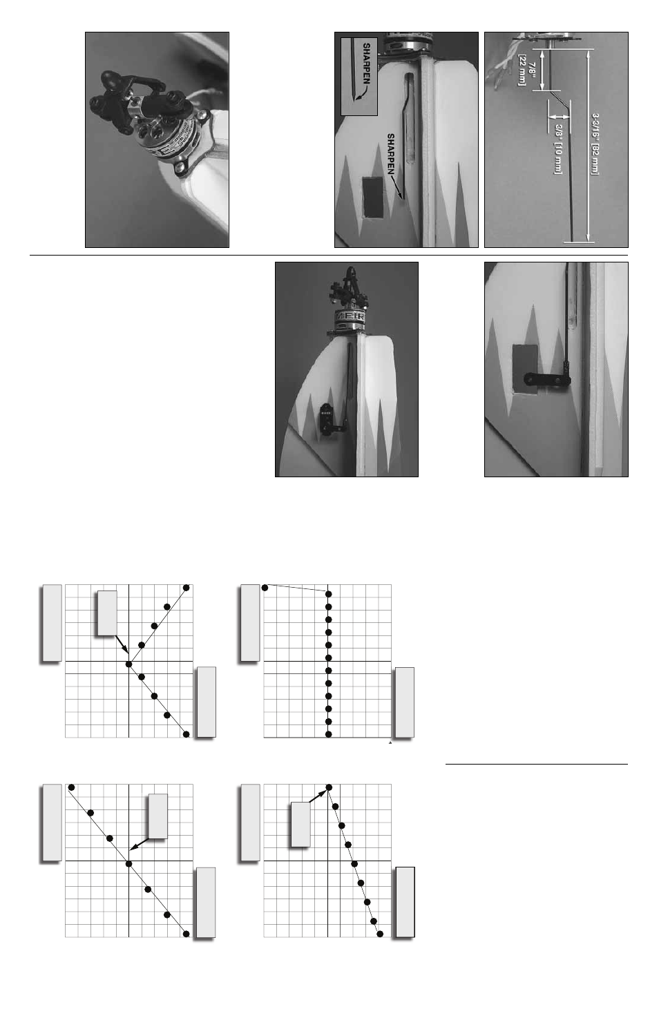
❏
4.
Cut the shaft to length as sho
wn abo
v
e
, b
ut be sure that
the b
lade holders are completely neutr
al (not pitching f
orw
ard
or bac
kw
ard) when doing this step
.
A
lso
, bend a slight angle
in the shaft to allo
w f
or it to e
xit the fuselage as sho
w
n.
Ne
xt,
tak
e a sanding bar or a piece of sandpaper and shar
pen the
end of the shaft bef
ore y
ou install the motor
.
❏
5.
Install the
V
-Pitch and Rimfire motor onto the plyw
ood
fire
w
all using (3) #4 x 3/8" w
ood scre
ws (not included).
Mak
e
sure the wire e
xits the slot correctly bef
ore tightening the
scre
w
s
.
Apply a drop of f
o
am saf
e
CA to the scre
ws to
ensure the
y will not bac
k out.
❏
6.
Locate one ser
v
o
ar
m and a z-bend from y
our FlatOut
par
ts tree
.
Clip the z-bend through the ser
v
o
ar
m.
Ne
xt,
press the shaft into the z-bend as sho
wn.
After y
ou ha
v
e
fir
mly pressed the shaft into the z-bend, apply a drop of
foam saf
e
CA to k
eep the shaft from slipping out.
❏
7.
Install y
o
ur ser
v
o
into the slot as sho
wn with a f
e
w
drops of f
oam saf
e
CA.
The installation is no
w complete
.
P
lease precede with
the radio set-up instructions on the ne
xt pa
g
e
bef
ore
y
ou attempt to fl
y the
V
-Pitc
h unit.
For models other than the Great Planes FlatOuts,
similar mounting methods might appl
y to y
o
ur model.
Ref
er to y
our model man
ufacturer f
o
r details.
V
-PITCH REPLA
CEMENT P
A
R
TS:
GPMG4490
......Replacement Blades (2)
GPMG4491
......Optional Carbon Fiber Blades (2)
GPMG4492
......Replacement Shaft w/2 Ball Bear
ings
GPMG4493
......Spinner/Collar
GPMG4494
......Scre
w
and Nut Set
GPMG4495
......Blade Holder w/Ball Bear
ings
GPMG4496
......Blade Holder Hub
Radio Set-Up f
or
V
-Pitc
h
1.
When setting up y
our
V
-Pitch unit in y
our r
adio
, be sure to
select the r
adio’
s helicopter prog
ra
m.
This will allo
w y
ou to
use pitch and throttle cur
v
e
s
.
2.
All of y
our channels will be as f
ollo
ws when using a
Futaba r
adio:
3.
Be sure to set an
“idle-up”
and a
“nor
mal”
flight mode in the
radio that can be changed with a s
w
itch that y
ou pref
er
.
This will allo
w y
ou to disab
le the
V
-Pitch with a s
w
itch.
“Normal”
Mode:
Acts just lik
e an
y other con
v
entional
fix
ed pitch aircr
aft.
“Idle-Up”
Mode:
Allo
ws y
ou to re
verse the thr
ust of the
propeller
.
W
hen y
ou ha
ve
y
our throttle stic
k in the center
position (0% throttle) y
ou will not ha
ve
an
y pitch.
As y
o
u
push the stic
k f
orw
ard (100% throttle) y
ou get positiv
e pitch
which allo
ws the air
plane to mo
ve
f
orw
ard.
When y
ou pull
the throttle stic
k bac
k (–100% throttle) it applies negativ
e
pitch to the b
lades and allo
ws the plane to go in re
verse
.
4.
Bef
o
re y
ou go an
y fur
ther
, unplug all 3 motor wires from
the ESC so y
ou can adjust the A
TV (end point) on the
pitch channel in the r
adio
.
Set the pitch A
TV to maxim
um
tr
a
v
el f
or positiv
e and negativ
e pitch.
5.
Please see the illustr
ations f
or setting up y
our r
adio’
s pitch
and throttle cur
v
es when using y
our
V
-Pitch with and
without go
v
e
rnor mode
.
K
eep in mind that these are just
star
ting points
.
Y
ou will need to fine tune each point per
y
our air
plane and flying pref
erences
.
•
Channel 1:
Aileron
•
Channel 2:
Ele
v
ator
•
Channel 3:
ESC/Throttle
•
Channel 4:
Rudder
•
Channel 5:
Pitch
With Governor
Mode Set in the ESC:
Throttle (Normal)
Pitch (Normal)
Throttle (Idle Up)
Pitch (Idle Up)
Positive Pitch
Neg
a
tive
Pitch
0%
10%
20%
30%
40%
50%
60%
70%
80%
90%
100%
L
o
w Throttle Stick
F
u
ll Throttle Stick
L
o
w Throttle Stick
F
u
ll Throttle Stick
Ne
g
a
tive Pitch
Positive Pi
tch
Zero Pitch
Zero Pitch
Zero Pitch
0%
10%
20%
30%
40%
50%
60%
70%
80%
90%
100%
0%
10%
20%
30%
40%
50%
60%
70%
80%
90%
100%
0%
10%
20%
30%
40%
50%
60%
70%
80%
90%
100%