Radio installation – Great Planes Piper J-3 Cub Fabric Covered ARF - GPMA1311 User Manual
Page 16
❏ ❏ 7. Screw the #2 x 1/2" self tapping screws into the
holes. Remove the screws and apply three drops of thin CA
to each hole to harden the underlying balsa. After the CA
has fully cured, attach the control horns using the #2 x 1/2"
self tapping screws.
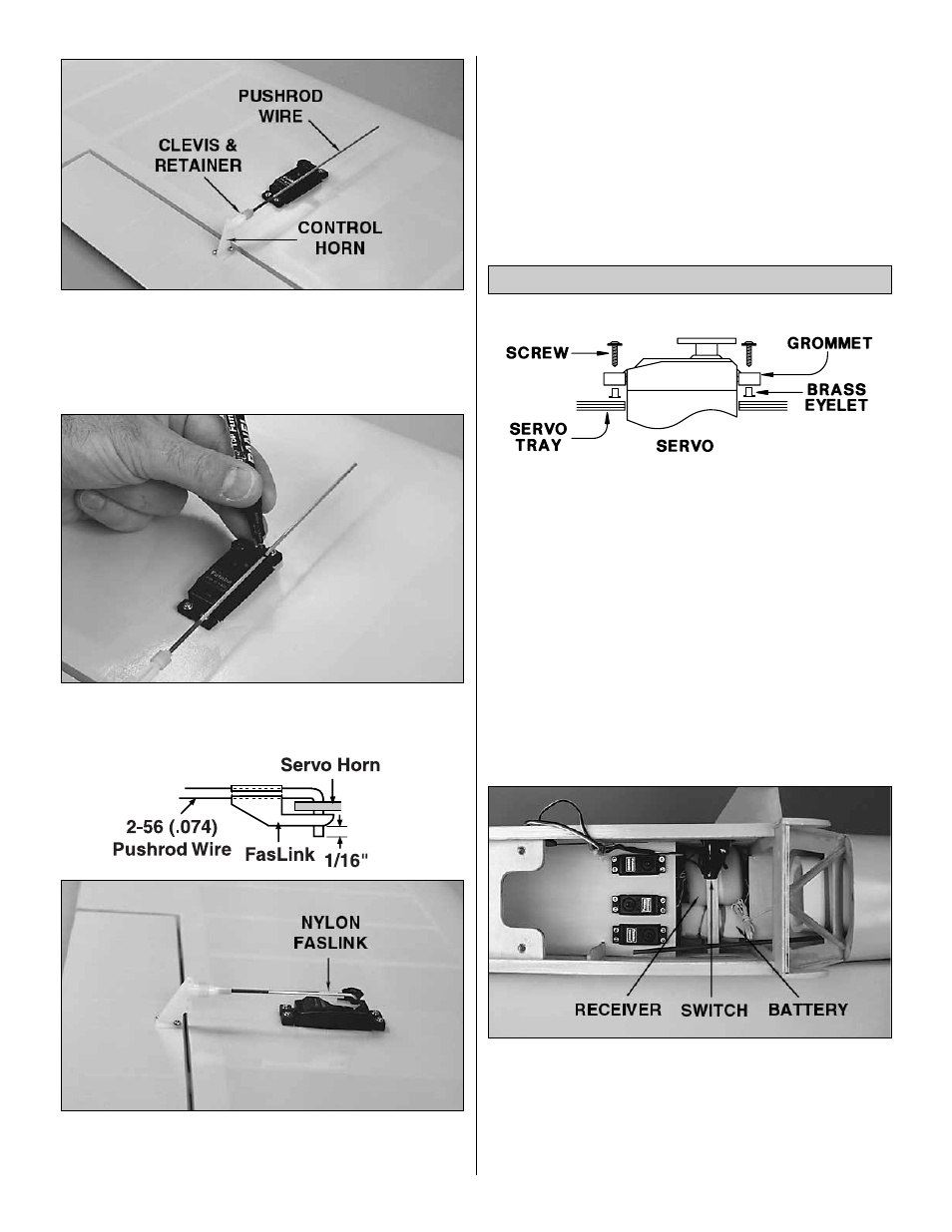
❏ ❏ 8. Use a felt-tip pen to mark the pushrod wire where it
crosses the holes in the aileron servo arm.
❏ 9. Bend the pushrod at the mark you made. Cut the
excess wire as shown in the sketch and connect the
pushrod to the servo arm with a nylon FasLink
Tm
.
❏ 10. Return to step 4 and connect the other aileron servo
to the other aileron the same way.
❏ 11. Turn the wing over. Locate the hole in the bottom of
the wing for the servo leads to exit. Remove the covering
from the holes using a sharp hobby knife. Pull the string out
of the 1/2" [13mm] holes in the bottom center section of the
wing to retrieve your aileron servo cords. Connect both
aileron servo cords to a "Y" harness.
❏ 1. Use the following sequence for mounting the servos
into the servo tray in the fuselage:
A. Install rubber grommets and brass eyelets in the
servos as shown in the sketch above.
B. Test fit the servos in the tray. Enlarge the openings
if needed to create a 1/32" [.8mm] gap around
the servo.
C. Mark servo mounting hole locations on the tray, then
drill 1/16" [1.6mm] pilot holes through each mark.
D. Mount the servos with the screws provided with
your radio system.
❏ 2. Install and hook up - following the manufacturer’s
recommendations - three servos, the receiver, switch and
battery as shown in the photo. We added a Great Planes
Switch Mount & Charge Jack (GPMM1000, not included) for
convenience and ease of use at the field, installed on the
side of the fuselage. Center the elevator, rudder and throttle
trims on the transmitter.
Radio Installation
16