Great Planes Mini Delta EP ARF - GPMA1172 User Manual
Page 2
GET
THE MODEL READ
Y
T
O
FL
Y
Chec
k the Contr
ol Directions
1.
With the tr
ansmitter and receiv
er on, chec
k all the control surf
aces to see if the
y are centered.
If
necessar
y,
adjust the cle
vises on the pushrods to center the control surf
aces
.
2.
Mak
e cer
tain that the control surf
aces and the throttle respond in the correct direction as sho
wn in
the diag
ra
m.
Set the Contr
ol
Thr
o
w
s
These are the recommended contr
ol surface thr
o
ws:
High Rate
Lo
w Rate
ELEV
A
T
OR
3/8”
[9mm]
up
3/16”
[4.5mm]
up
3/8”
[9mm]
do
wn
3/16”
[4.5mm]
do
wn
AILER
ONS
3/8”
[9mm]
up
3/16”
[4.5mm]
up
3/8”
[9mm]
do
wn
3/16”
[4.5mm]
do
wn
IMPOR
T
ANT
:
F
or a flying wing to be aerodynamically stab
le
, the neutr
al position of the ele
vons needs to
be r
aised from neutr
al.
T
o
achie
ve
pitch stability
, place a r
uler on the bottom of the wing and adjust the
neutr
al position of the ele
vons so that the tr
ailing edge of each ele
von is r
aised 3/32”
[2mm].
Balance the Model
(C.G.)
More than an
y other f
actor
, the
C.G.
(balance point) can ha
v
e
the
greatest
eff
ect on ho
w a model flies
, and ma
y deter
mine whether or not
y
our first flight will be successful.
If y
ou v
alue this model and wish to enjo
y
it f
or man
y
flights
,
DO NO
T O
VERLOOK
THIS IMPOR
T
ANT
PR
OCEDURE.
A model that is not proper
ly balanced will be unstab
le
and possib
ly unfly
ab
le
.
IMPOR
T
ANT
:
Mini Delta EP has been
e
xtensivel
y
flo
wn
and tested to arr
iv
e at the thro
ws at which it flies best.
Flying
y
our model at these thro
ws will pro
vide y
ou with the g
reatest
chance f
or successful first flights
.
When chec
king the CG the model should be in ready-to-fly condition with all
of the systems in place including the batter
y.
The C
.G.
is located 5.4”
[136mm]
bac
k from the fuselage along the leading edge of the wing.
Change the
location of the motor batter
y to balance y
our air
plane at that point.
PREFLIGHT
Identify Y
our
Model
No matter if y
ou fly at an AMA sanctioned R/C club site or if y
ou fly
some
where on y
our o
wn, y
ou should alw
a
ys ha
v
e
y
our name
,
address
, telephone n
umber and AMA n
umber on or inside y
our
model.
It is
required
at all AMA R/C club flying sites and AMA
sanctioned flying e
v
ents
.
Char
g
e
the Batteries
F
ollo
w the batter
y
charging instr
uctions that came with y
our r
adio
control system to charge the tr
ansmitter batter
ies
.
Do the same f
o
r
y
our motor batter
ies
.
Rang
e Chec
k
Ground chec
k the oper
ational r
ange of y
our r
adio bef
ore the first
flight of the da
y.
With the tr
ansmitter antenna collapsed and the
receiv
er and tr
ansmitter on, y
ou should be ab
le to w
alk at least 100
feet a
w
a
y
from the model and still ha
v
e
control.
ASSEMBL
Y INSTR
UCTIONS
FL
YING
Mini Delta EP is a g
reat-flying model that flies smoothly and predictab
ly
.
Mini Delta EP does not, ho
w
e
v
e
r, possess the self-rec
ov
e
ry
char
acter
istics of a pr
imar
y R/C tr
ainer and should be flo
wn only b
y
e
xper
ienced R/C pilots
.
T
akeoff
Hold the air
plane from the fuselage under the wing and point it slightly
“up”.
Remember to launch the air
plane into the wind.
App
ly
3/4 to full throttle and launch the plane with moder
ate f
o
rce
.
Flight
This plane can fly f
a
st f
or about 6 min
utes when flo
wn at full throttle
.The air
plane is f
ast b
ut predictab
le
.
Get used to the pl
ane at lo
w
rates bef
ore s
witching to high r
ates as the roll and pitch r
ates will become e
xtremely quic
k on high r
ates
.
Flight times will increase if throttle management is pr
acticed.
The Mini Delta EP can maintain altitude at 1/3 throttle and it c
an fly
most maneuv
ers at ½.
The Mini Delta EP is still stab
le and predictab
le at slo
w speeds and it also allo
ws the pilot more time to
think
about its reactions
.
The Mini Delta EP is capab
le of loops and rolls
, in
v
e
rted flight and an
y other maneuv
er that does not require r
u
dder
.
On high r
a
tes
,
it can also perf
or
m some stalling maneuv
ers lik
e w
alls
.
Landing
T
o
initiate a landing approach, lo
w
er the throttle and let the air
plane lose some altitude
.
When the model is 2-3 f
e
et [60-90 cm
] from
the g
round, apply up ele
v
ator to b
leed off speed and land while maintaining the same heading.
GOOD LUCK AND GREA
T FL
YING!
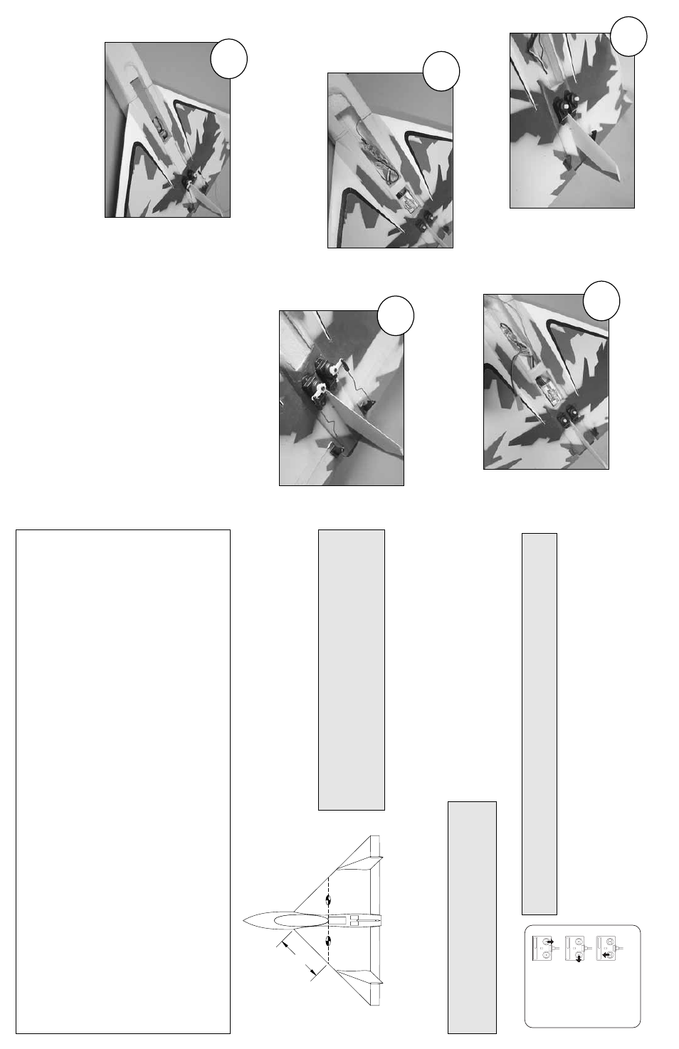
Glue the tw
o ser
v
os in place with f
o
am saf
e CA
as sho
wn.
Install the receiv
er and the speed control in
the fuselage
.
Mak
e a small hole on the side of the fuselage
and slide the receiv
er antenna through it.
T
a
pe
the antenna to the leading edge of the wing.
Center the ser
v
os with the r
adio
.
Install the
ser
v
o
ar
ms
, the pushrods and the f
aslinks
.
Install the motor batter
y,
canop
y and receiv
er
hatch.
Adjust the ele
v
ons' neutr
al point, the
thro
ws and the CG.
Place the decals on the plane using the photo
in the front page as a guide
.
Go fl
y!
FULL THROTTLE
RIGHT ELEVON MOVES UP
LEFT ELEVON MOVES DOWN
ELEVONS MOVE UP
4-CHANNEL
TRANSMITTER
RADIO SETUP
TRANSMITTER
4-CHANNEL
TRANSMITTER
4-CHANNEL
2
5
4
3
1
5.4" [136mm]5.4
" [
13
6m
m
]