Cerwin-Vega Professional Audio Mixer CVM-1022 User Manual
Page 9
9
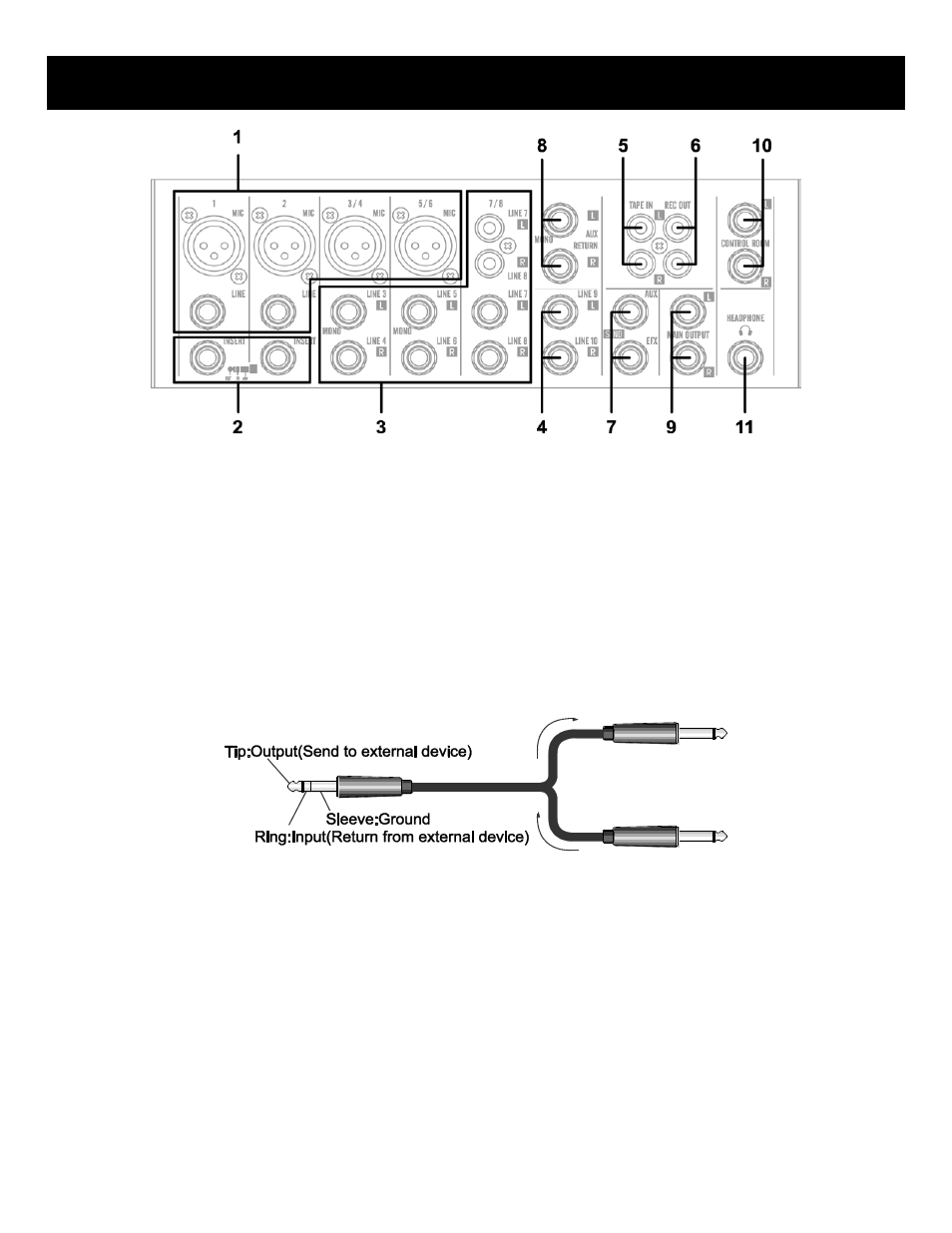
FRONT PANEL CONTROLS – INPUT/OUTPUT CONNECTORS
(1). Channel Input Jacks
MIC JACKS
A 3-pin XLR-type connector is used for balanced low impedance microphone inputs. (pin 1: sleeve, 2: hot, 3:cold)
BALANCED LINE IN JACKS
A standard 1/4” phone jack is used for balanced or unbalanced line level signals. Examples of line level signals include
most electronic keyboards, synthesizers, turn-tables (with appropriate pre-amps), tape decks and the line outputs from
other mixers.
(2). CHANNEL INSERT I/O JACK
These are input/output jacks located between the head-amplifier and the high pass filter. These jacks allow you to use
graphic equalizers, compressors, noise filters, or other devices.
(3, 4). CHANNEL INPUT JACKS
These are unbalanced stereo line input jacks. Two jack types are provided phone type and RCA pin type.
(5). TAPE IN JACKS
These RCA pin jacks input a stereo sound source. Use these jacks when you want to connect a CD or DAT directly to the
mixer for monitoring.
NOTE: You can adjust the signal level using the TAPE IN control in MAIN control section.
(6). REC OUT JACKS
The REC OUT jacks send the pre-fader signal from the master bus for recording by the tape deck.