GME SPK002W User Manual
Page 2
PAGE 2
TECHNICAL SPECIFICATION AND CUTTING TEMPLATE
SPK001/SPK002
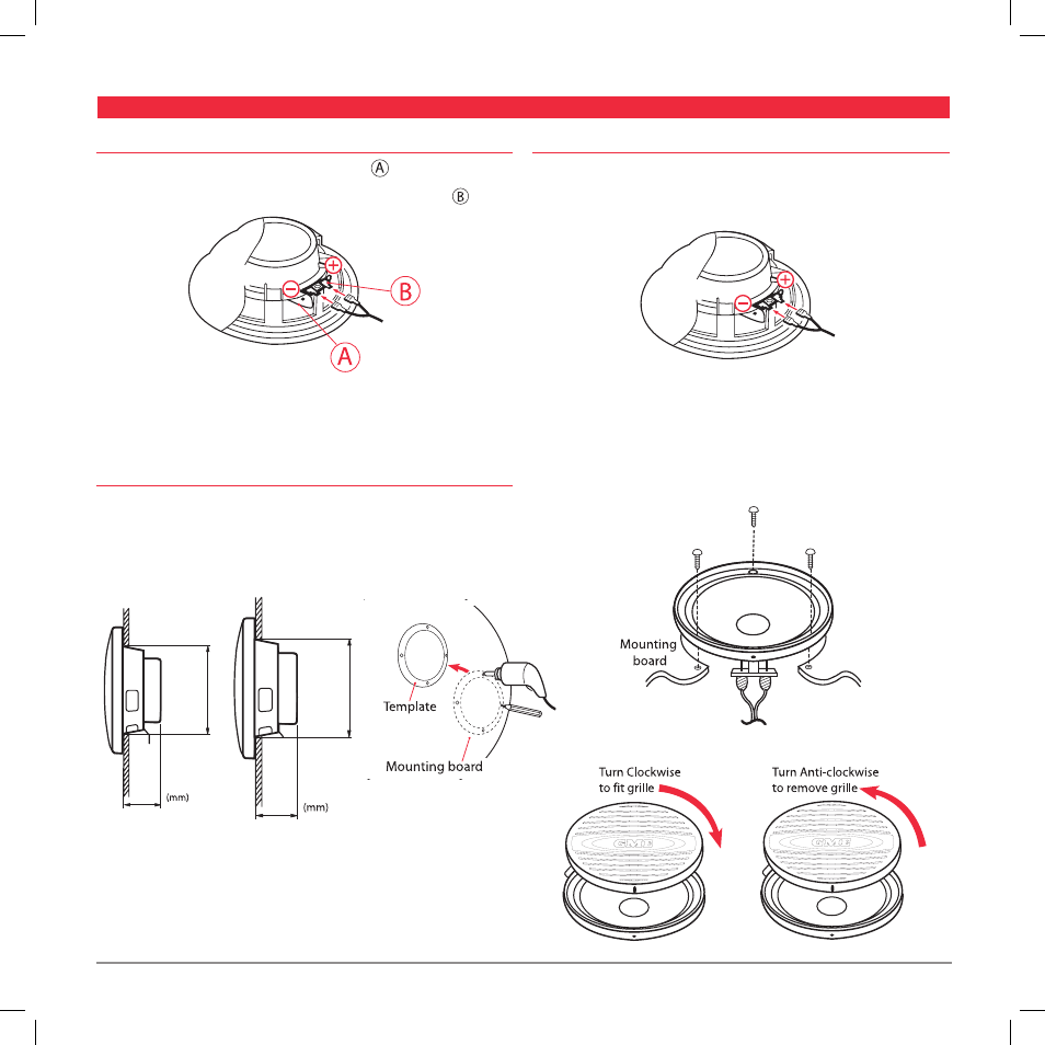
MoUnTinG insTrUcTions
To Amp
/Stereo
spK001
spK002
precaUTions
1 Please avoid contact with inside speaker wire
2 Do not change the polarity of the speaker terminal assembly
3 Make sure lead and speaker terminals do not contact metal.
4 When making connections, please refer to the instruction manual
of marine stereo used.
MoUnTinG
1. When mounting the SPK001 in the kick panel, make sure there
is a clearance of 55 mm (2.17”) behind the well.
When mounting the SPK002 in the kick panel, make sure there
is a clearance of 65 mm (2.56”) behind the well.
2. Push out the template from this leaflet and use to mark the position
of the mounting screws and the outline of the speaker hole. Drill the
mounting holes and cut the hole for the speaker.
connecTinG
1. Attach the speaker wires (supplied) to the speaker terminals be sure to
connect the striped wire to the negative (–) terminal, and the other wire
to the positive (+) terminal of the speaker.
Connect the other end of the speaker wires to your amplifier/stereo.
2. Remove the speaker grille (turn anti-clockwise). Fit the speaker into the
cutout and secure the speaker using the screws (supplied).
Replace the speaker grille on the speaker (turn clockwise) until the grille
locks into place.
55
65
145
123
(2.17”)
(4.8”)
(5.7”)
(2.56”)