Specifications, Installation – GME RM600D User Manual
Page 3
RM600D
INSTRUCTION MANUAL
PAGE 3
sPECIFICATIONs
ELECTRICAL
Supply Voltage: Volt Nominal
0.5-5.6 Volt Max. range
Negative earth
Current Consumption: Muted <00 mA
Full Volume 700 mA
ENVIRONMENTAL
Temperature Range: -0˚C to 55˚C
Solar Radiation: Case UV stabilised
Water & Dust Resistance: TP67 excluding external
cabling
Compass Safe Distance: 300 mm
MECHANICAL
Dimensions: 64(W) x 65(H) x 55(D) mm
Weight: 450 grams
AUDIO OUTPUT POWER
External 4 Ohm Speaker: 4 Watts average
Internal Speaker: Watts average
EXTERNAL CONNECTIONs
Microphone: 6 pin RJ Socket
D.C. Supply: pin Polarized Blade Socket
External Speaker: 3.5 mm mini phono line
socket (mono)
OVERCURRENT PROTECTION
Fuse: Inline Amp 3 AG
INsTALLATION
INsTALLING THE UNIT
After choosing your location, hold the unit with the
mounting bracket attached into the desired position and
mark the location with a pencil. Remove the mounting
bracket from the radio and drill the mounting holes. Bolt or
screw the bracket in place using hardware suitable for the
mounting surface. The unit is supplied with stainless steel
screws; however, if the mounting surface is unsuitable for
screws you may need to replace these with stainless steel
bolts. Remember the fixings for overhead mounted units
may have to withstand heavy pounding when the vessel is
in rough water or being towed on a trailer.
sELECTING A LOCATION
It is advisable to spend a little time selecting the best
location for your RM600D. The mounting bracket can be
rotated above, below or behind the radio enabling the radio
to be mounted in a wide range of locations. In addition,
using the optional flush mounting kits (MK600, MK00,
MK00) the RM600D can be mounted directly in a panel or
dashboard. The flush mounting kits allow for installation or
replacement of any existing VHF radio.
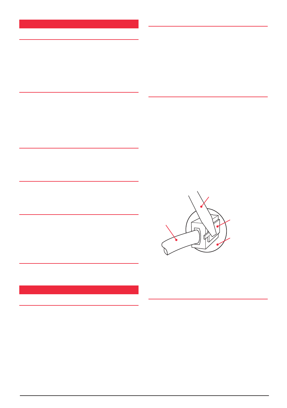
REPLACING THE MICROPHONE
It is recommended that the microphone be left permanently
connected to the RM600D, but if it must be disconnected,
proceed as follows:
. Insert a small screw driver between the rubber boot
and the lip of the raised area on the front panel.
. Ease the rubber boot out of the cable entry hole and
slide it along the cable away from the front panel.
3. Identify the plug locking lever, work the screwdriver
blade behind it and move the lever towards the plug
body. At the same time gently pull the plug from the
socket. (see diagram below).
If required, replacement microphones are available with
plug and rubber boot already fitted.
WATER PROOFING CONNECTIONs
Although the RM600D itself is designed to resist the
ingress of water, the cable connectors are not completely
waterproof. After installation, the speaker and remote
connectors should be wrapped in waterproof tape or similar
to minimise the risk of corrosion or water damage. Do
not use normal electrical tape as this will not provide an
adequate seal against water. The connectors should then
be positioned where they are not directly exposed to the
elements.
Cable
Screwdriver
Locking Lever
move to left to
release Plug
Cable entry hole