Trimmer setting (initial), Gain setting, Gain setting with t8uaps example 2) – Futaba GYA351 User Manual
Page 3: Gain setting with t8uaps example 3), Example of gain setting using t9zap), Power on procedure, Gyro operation direction check, Gyro connection, Gain setting with t8uaps example 1)
When there is no vacant channel that can be used for gain switching,
"Standard setting" cannot be performed. See "Beginner setting".
When gyros are installed in two or three axis, and there are not enough
vacant channels, use a branch cord to simultaneously switch the gain of
two axis.
3. Trimmer setting (Initial)
Set the gyro gain trimmer to the 100% position.
Set the control gain trimmer to about the 100% position.
4. Gain setting
Set the gain as described below.
100% 100%
(Gain setting with T8UAPS example 2)
The following describes how to use channels 5, 7, and 8 to switch
the gain of the rudder, aileron, and elevator axis. (When GYA350
being used in the rudder and elevator.)
1.Call the transmitter 5ch ATV screen and
make the following setting:
- Set the CH5 switch rate for both directions to
70%. This sets the gyro gain to 50%.
•In the switch forward position, the gyro operates
in the AVCS mode and in the switch backward
position, the gyro operates in the Normal mode.
2.Call the transmitter PMIX-1 screen, and make
the following settings:
- Activate PMIX1.
- Set master channel to OFS.
- Set slave channel to CH7.
- Set mixing rate to +70%.
- Select switch SW-E.
- Select switch direction DOWN.
3.Call the transmitter PMIX-2 screen, and make
the following settings:
- Activate PMIX-2.
- Set master channel to OFS.
- Set slave channel to CH7.
- Set the mixing rate to -70%.
- Select switch SW-E.
- Select switch direction UP.
4.Lock the transmitter CH7 knob in
the 0% position. This sets the
aileron axis gyro gain to 50%.
•When switch SW-E is in the forward
position, center position, and
backward position, the GYA350
gyro operates in the AVCS, OFF,
and Normal modes, respectively.
5.Call the transmitter PMIX-3 screen, and make
the following settings:
- Activate PMIX-3.
- Set master channel to OFS.
- Set slave channel to CH8.
- Set mixing rate to +70%.
- Select switch SW-E.
- Select switch direction DOWN.
6.Call the transmitter PMIX-4 screen, and make
the following settings:
- Activate PMIX-4.
- Set master channel to OFS.
- Set slave channel to CH8.
- Set mixing rate to -70%.
- Select switch SW-E.
- Select switch direction UP.
7. Lock the transmitter CH8 knob in
the 0% position.
This sets the elevator axis gyro
gain to 50%.
•When SW-E is in the forward,
center, and backward positions, the
GYA350 operates in the AVCS, OFF,
and Normal mode, respectively.
Normal
OFF
AVCS
Normal
OFF
AVCS
CH7
knob
CH8
knob
(Gain setting with T8UAPS example 3)
The following describes how to use CH7 to switch the aileron and elevator
gain and CH8 to switch the rudder axis gain. (When GYA350 being used
in the rudder and elevator.)
The aileron and elevator gyros gain switching connector is connected to
receiver CH7 by branch cord. When air brake is ON, the aileron and
elevator axis gyros must be set to the Normal mode.
1.Call the transmitter PMIX-1 screen, and make
the following settings:
- Activate PMIX1.
- Set master channel to OFS.
- Set slave channel to CH7.
- Set mixing rate to +70%.
- Select switch SW-C.
- Select switch direction UP.
2.Call the transmitter PMIX-2 screen, and make
the following settings:
- Activate PMIX-2.
- Set master channel to OFS.
- Set slave channel to CH7.
- Set the mixing rate to -70%.
- Select switch SW-C.
- Select switch direction C/DN.
3.Lock the transmitter CH7 knob in
the 0% position. This sets the
aileron and elevator gyro gain to
50%.
•When switch SW-C is in the up,
center, and down positions, the
GYA350 operates in the AVCS,
Normal, and air brake ON modes,
respectively.
When you want to set the gain of
the aileron and elevator gyros
independently, adjust the gyro
gain trimmer on the gyros
individually.
4.Call the transmitter PMIX-3 screen, and make
the following settings:
- Activate PMIX-3.
- Set master channel to OFS.
- Set slave channel to CH8.
- Set mixing rate to +70%.
- Select switch SW-E.
- Select switch direction DOWN.
5.Call the transmitter PMIX-4 screen, and make
the following settings:
- Activate PMIX-4.
- Set master channel to OFS.
- Set slave channel to CH8.
- Set mixing rate to -70%.
- Select switch SW-E.
- Select switch direction UP.
6. Lock the transmitter CH8 knob in
the 0% position.
This sets the rudder axis gyro
gain to 50%.
•When SW-E is set to the forward,
center, and backward positions, the
GYA350 operates in the AVCS, OFF,
and Normal modes, respectively.
AVCS
Normal
Normal
Air Brake
Normal
OFF
AVCS
CH7
knob
CH8
knob
(Example of gain setting using T9ZAP)
The following describes how to use vacant channels 5, 7, and 8 to
switch the gain of the rudder, aileron, and elevator axis. (When
GYA350 being used in the rudder and elevator.)
+T1
+J1
AIL
+T3
+J3
ELE
+T2
+J2
THR
+T4
+J4
RUD
+SF
GEA
+LD
FLP
+SE
AU1
+SE
AU2
END
SEL
CTR
TRM
FUNCT CTRL
FUNCT CTRL
END
AIL
ELE THR RUD GEA FLP AU1 AU2
ATV
ATV
NXT
NORMAL
GEA
70 %
70 %
: MODE
: CHANNEL
: RATE A
A
INPUT
SRV
B
: RATE B
1.Call the transmitter
function control functions
screen, and make the
following settings:
- Set switch SF to
GEA(5CH) and switch SE
to AU1(7CH) and
AU2(8CH), respectively.
2.Call the transmitter ATV
function screen, and make
the following settings:
- Select GEA(5CH) and
set both RATEA and
RATEB to 70%.
- Set AU1(7CH) and
AU2(8CH) to 70% rate
similarly.
This sets the gain of the aileron,
elevator and rudder axis gyros to
50% each.
•When switch SW(E) is set to the
forward, center, and backward
positions, the GYA350 operates in the
AVCS, OFF, and Normal modes,
respectively. When switch SW(F) is set
to the forward and backward positions,
the rudder axis gyro operates in the
AVCS and Normal modes,
respectively.
Normal
OFF
SW(E)
SW(F)
AVCS
Normal
AVCS
5. Power ON procedure
Turn on the transmitter power, then turn on the receiver and gyro power.
Initialization is performed automatically for about three seconds after the
gyro power comes on. Do not move the aircraft during this period. During
initialization, the gyro monitor LED flashes. When the gain selector switch is
set to the AVCS position, the monitor LED changes to a steady light. When
the gain selector switch is set to the Normal position, the LED goes off.
6. Gyro operation direction check
Tilt the aircraft about the control axis, and check if the gyro moves in the
direction opposite the tilt direction.
If the gyro moves in the opposite direction, switch the gyro direction of
operation selector switch.
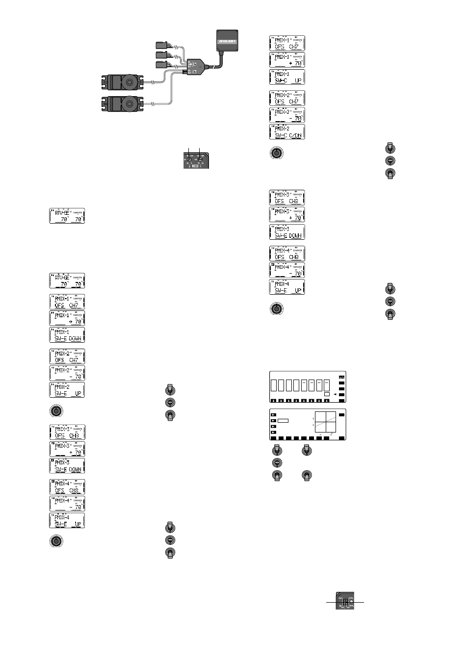
2. Gyro connection
• Connect to the gain switching channel.
• Connect to the receiver output of ch1.
• Ch1 servo.
• Connect to the receiver output of ch6.
• Ch6 servo.
(Gain setting with T8UAPS example 1)
The following describes how to use the channel 5 switch to switch
the aileron axis gain. (When GYA351 used independently.)
1.Call the transmitter 5ch ATV screen and
make the following setting:
Set the rate of both directions of the CH5
switch to 70%. This sets the gyro gain to 50%.
•In the switch forward position, the gyro operates in the
AVCS mode and in the switch backward position, the gyro
operates in the Normal mode.
Gyro direction of operation
selector switch (ch1)(DIR.A)
Gyro direction of operation
selector switch (ch6)(DIR.F)