Futaba R7003SB User Manual
Page 2
WARNING
Do not perform the linking procedure while the motor's main wire connected
or the engine is operating as it may result in serious injury.
7HEN
the receiver is properly linked to the transmitter.
0LEASE
)F
transmitter.
WARNING
Don't touch wiring.
* There is a danger of receiving an electric shock.
$ONgT
7HEN
$ONgT
FUTABA CORPORATION
1080 Yabutsuka, Chosei-mura, Chosei-gun, Chiba-ken, 299-4395, Japan
Phone: +81 475 32 6982, Facsimile: +81 475 32 6983
Link to the transmitter
Easy Link ID allows FASSTest receivers to link to compatible transmitter without pressing
the link button on the receiver.
1
meter).
2
4URN
3
4
7HEN
is complete.
* Refer to the transmitters operation manual for complete details on how to place the transmitter into the
linking mode.
ESTABLISHING
1
4URN
2
P
RESS
*It becomes the mode which makes a mistake in exceeding 10 seconds. In that case, carry out power
supply OFF and redo.
3
4
%ACH
5
7HEN
,INK
6
7HEN
7
P
LEASE
6/,
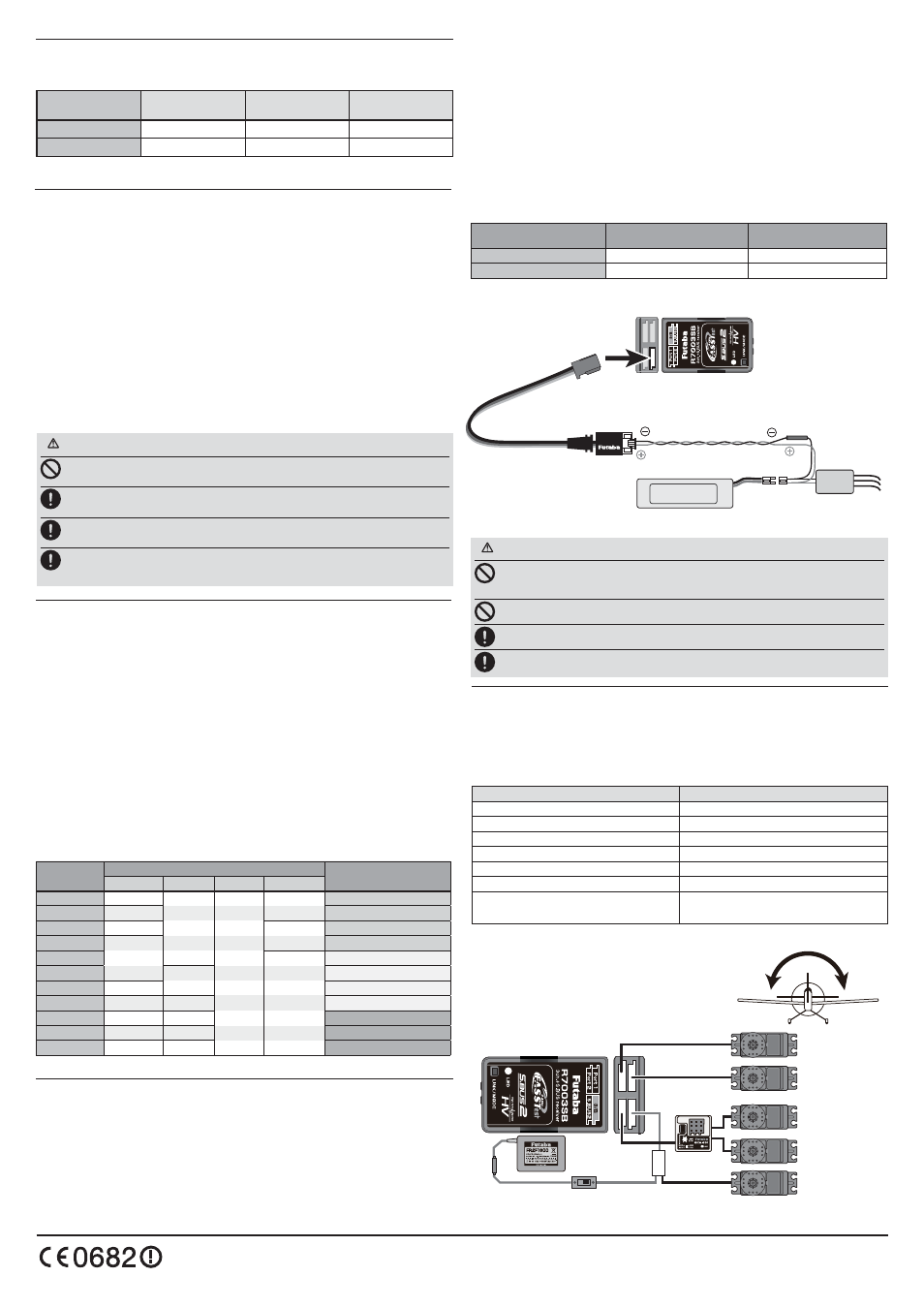
Measurement of Extra Voltag
R7003SB can display the voltage of a receiver battery on a transmitter.
Furthermore, the following procedures are required in order to display the voltage of
another battery (Drive battery etc.).
1
2
R
3"
3
!ccording to the manual of #! 26). , battery wiring is branched and it
connects.
4
Channel Modes
The R7003SB is capable of changing its channel allocations as described in the table
below. Please choose the mode which suited the use in the following procedure from the
11 modes.
1
[
4RANSMITTER
2
4URN
the button can be released.
3
4
%ACH
[R
EFER
5
7HEN
-ODE,INK
6
7HEN
7
Please cycle the receiver power off and back on again after changing the
#HANNEL
S.BUS2
S.BUS2 extends S.BUS and supports bidirectional communication. Sensors are connected
to the S.BUS2 port.
/NLY
SERVOS
R7003SB CH Mode table
)87$%$ &25325$7,21
When using the R7003SB Receiver with the GYA430,
GYA431 and CGY750
The following table corresponds to the gyro's functions. A port can be used effectively.
The servo which a gyro controls is connected to a gyro.
* Please refer to the description of each gyro manual.
Gyro control CH
CH Mode
Rudder
D,E
Elevator
F
Aileron
G
Elevator+Rudder
H
Aileron+Rudder
I
Aileron+Elevator
J
Aileron+Elevator+Rudder
or CGY750
K
S.BUS Gyro Goup table
ZLWKH[WHUQDOSRZHU
LQSXWPXVWEHOHVVWKDQ9
7R0RWRU&RQWUROOHU
RU6HUYR
%UDQFK
)XVH
%ODFNOLQH
5HGOLQH
0RWRU
&RQWUROOHU
(;792/&$%/(
,WLVDWWDFKHGWR56%
2SWLRQ
(;792/&$%/(
WR3RUW
,WFKDQJHVLQWR(;792/0RGH
56%
WR0RWRU
3RZHU%DWWHU\RU
DQRWKHUSRZHUVXSSO\
IRUVHUYRV