Ch group table, S.bus gyro group table, Operation normal/high speed mode select – Futaba R6303SB User Manual
Page 2: How to set the operation channel
Operation Normal/High Speed Mode Select
The operation mode is set on "Normal Mode" from the factory. To
change the mode please follow the steps below.
1
Turn off the receiver.
2
Press and hold the
Link/Mode button and turn on the receiver.
Press and hold the button for more then 1 second. The LED
will start to flash and will indicate the current status.
3
Release the button.
4
Turn off the receiver.
By following these steps the receiver modes can be switched back and
forth between normal and high speed modes.
0 to 1 sec.
More than 1 sec.
0 sec.
1 sec.
Press and Hold
Turn on the receiver.
No function
Showing the CURRENT
mode with blink.
Red Blink = Normal
Green/Red Blink =
High Speed
Solid as the mode changed.
Red Solid = Normal
Green/Red Solid = High
Speed
(Become
Red after
1second)
(
Function)
To change the mode between
Normal and High Speed
(
LED Status)
Please check the operation mode by observing the LED when turning on
the receiver. The best way to confirm the mode you are on is to make sure
that there are no other
FASST transmitters turned on around you.
When turning on the receiver, the LED will be;
• Red when on "Normal mode"
• Green and Red (making orange) when on "High Speed mode". (After 2
seconds, the LED will change to red.)
If there are any FASST transmitters turned on around the receiver, the
LED may show the above status, but just for a brief moment and then
change to the status indicated in the "LED indication" table below.
How to Set the Operation Channel
It is possible to choose the operation channel mode of the port 1 and 2
from 7 setting groups.
1
Turn on the receiver. (At this moment, the transmitter should
be off.) Then, ensure the
LED is lit in RED or flashing green
light.
2
Press and hold the
Link/Mode button more than 5 seconds.
3
Release the button when the
LED blinks RED and GREEN
simultaneously.
4
The receiver is now in the "Operation CH Set" mode. At this
moment, the
LED indicates current set status through flashing
a pattern that corresponds to the CH group.
*Cannot exit this CH setting mode before the operation mode is fixed.
**See the below table that shows correspondence between "CH group" and way
of flashing LED.
***Default CH mode is "Group 1".
5
By pressing the
Link/Mode button, the operation CH is switched
sequentially as "group 1" "group 2" "group 3"....
6
The operation mode will be set by pressing the
Link/Mode
button more than 2 seconds at the desired CH group.
7
Release the button when the
LED blinks RED and GREEN
simultaneously. After releasing the button, the RED and
GREEN
LED are lit 1 second simultaneously. Then, the
operation CH is fixed.
8
After confirming the operation CH mode is changed, turn off
and back on the receiver power.
*The “Operation CH Set” mode cannot be changed during the receiver
communicates to the transmitter.
FUTABA CORPORATION
1080 Yabutsuka, Chosei-mura, Chosei-gun, Chiba-ken, 299-4395, Japan
Phone: +81 475 32 6982, Facsimile: +81 475 32 6983
©FUTABA CORPORATION 2012, 4 (1)
LED Indication
Green
Red
Status
Solid
Solid
Initializing when on "High Speed mode"
Off
Solid
No signal reception
Solid
Off
Receiving signals
Blink
Off
Receiving signals but ID is unmatched
Alternate blink
Unrecoverable error (EEPROM, etc.)
CH group table
CH group
LED blink
Port 1
Port 2
group 1
Red time
CH1
CH2
group 2
Red time
CH1
CH4
group 3
Red time
CH2
CH4
group 4
Green time
CH1
CH5
group 5
Green 2 time
CH2
CH7
group 6
Green 3 time
CH4
CH8
group 7
Red/Green time
CH11
CH12
group 8
Red/Green 2 time
not used
not used
group 9
Red/Green 3 time
not used
not used
Initial setting is group 1.
The groups 8 and 9 are not usually used.
3CH port and S.BUS port never change.
When using the R6303SB Receiver with the
GYA430, 431 and CGY750
The following table corresponds to the gyro's functions. A port can be
used effectively. The servo which a gyro controls is connected to a gyro.
* Please refer to the description of each gyro manual.
S.BUS gyro group table
Gyro control CH
CH group
Rudder
group 1
Elevator
group 2
Aileron
group 3
Elevator+Rudder
group 4
Aileron+Rudder
group 5
Aileron+Elevator
group 6
Aileron+Elevator+Rudder
or CGY750
group 7
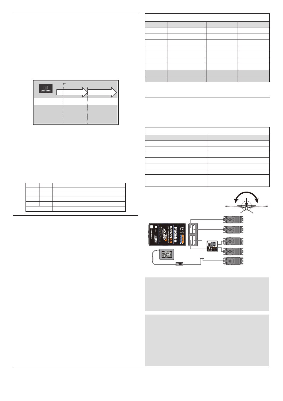
When S.BUS is used
* Set the channel of
S.BUS servos by using an SBC-1 channel changer, CIU-2
USB serial interface or the programming software in the
18MZ transmitter.
*
Can also be used together with conventional servos. However, conventional
servos cannot be used by the
S.BUS output.
*
When using servos with a remote battery pack, use
S.BUS Hub with Cable
(2-way/remote battery pack use).
Please refer to the instruction manual of
S.BUS Hub with Cable (2-way/re-
mote battery pack use) for the connection method.
*Turn on the power in transmitter→receiver order. In addition, always check
the operation of all the servos before flight.
*Do not insert or remove the servo connector while the receiver power is ON.
What is S.BUS?
S.BUS is different from conventional radio control systems in that it
uses data communication to transmit control signals from the receiver
to a servo, gyro, or other S.BUS compatible devices. The S.BUS
devices only execute only those comands for there own set channel.
This is why a single signal can be used to connect multiple servos.