Link to the transmitter – Futaba R2008SB User Manual
Page 2
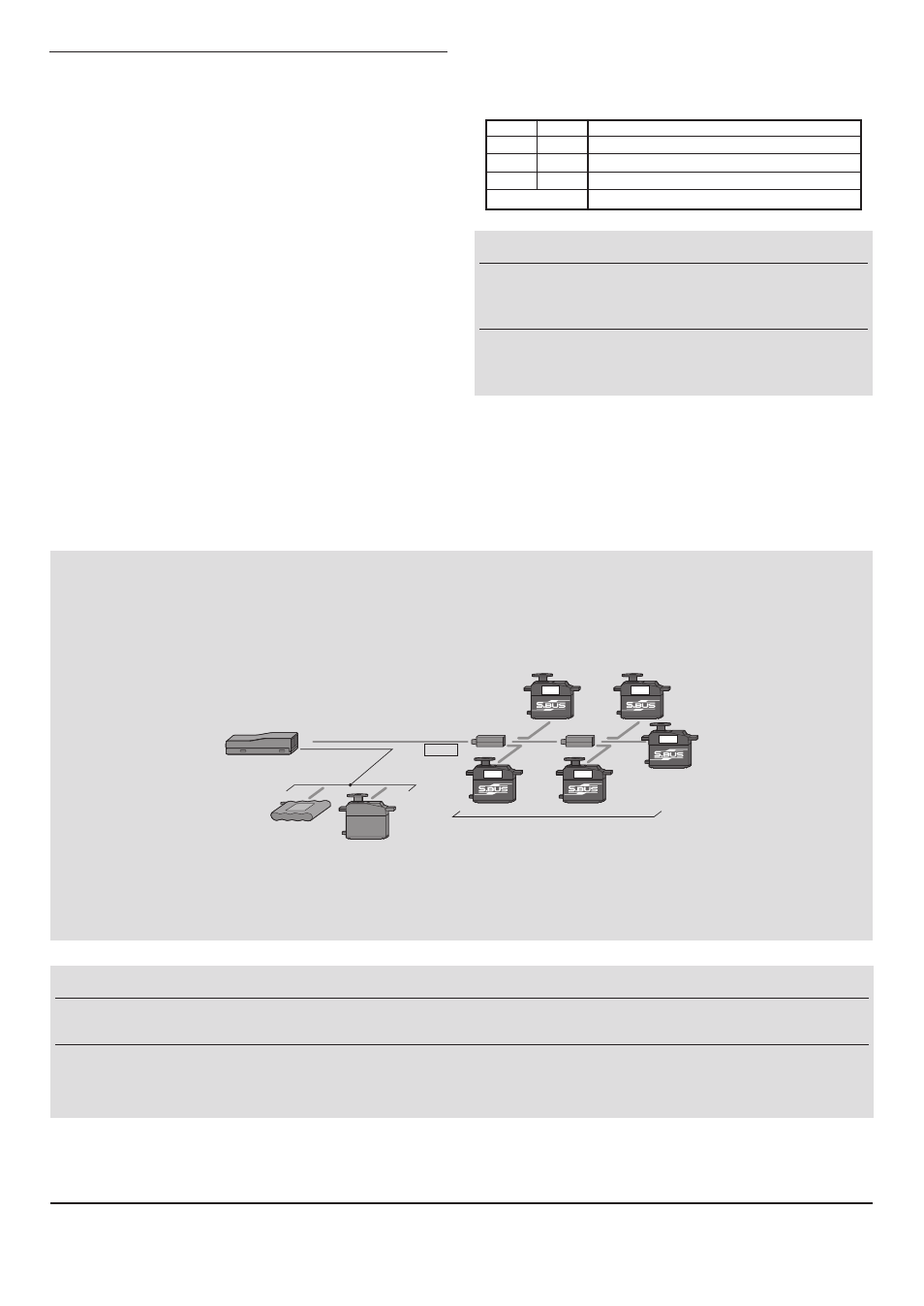
What is S.BUS?
Different from conventional radio control systems the S.BUS
system uses data communication to transmit control signals
from a receiver to a servo, gyro, or other S.BUS compatible
device. This data includes commands such as “move the
channel 3 servo to 15 degrees, move the channel 5 servo to
30 degrees” to multiple devices. The S.BUS devices execute
only those commands for their own set channel. For this
reason, it can be used by connecting multiple servos to the
same signal line.
[Connection by S.BUS system]
S.BUS hub
S.BUS hub
S.BUS output
S.BUS
Ch output/
Battery terminal
R2008SB
Battery
S.BUS servo
Conventional
servo
1ch
3ch
2ch
5ch
4ch
* Set the channel at the
S.BUS servos by using an SBC-1 channel changer or a CIU-2 USB serial interface.
*
Can also be used together with conventional servos. However, conventional servos cannot be used by the
S.BUS output.
*
When using servos with a remote battery pack, use
S.BUS Hub with Cable (2-way/remote battery pack use).
Please refer to the instruction manual of
S.BUS Hub with Cable (2-way/remote battery pack use) for the connection method.
WARNING
Do not perform the linking procedure with
motor's main wire is connected or the engine is
operating as it may result in serious injury.
When the linking is done, please cycle receiver
power and check if the receiver to be linked is
really under the control by the transmitter to be linked.
WARNING
Turn on the power on transmitter
→ receiver in order. In addition, always check the operation of all the
servos before flight.
Do not insert or remove the servo connector while the receiver power is ON.
Since the S.BUS servo switches the operation mode automatically according to the type of signal (S.BUS signal/PWM signal) from the
receiver, if the connector is inserted or removed while the power is ON, an S.BUS connected servo will be erroneously recognized and may
stop.
FUTABA CORPORATION
1080 Yabutsuka, Chosei-mura, Chosei-gun, Chiba-ken, 299-4395, Japan
Phone: +81 475 32 6982, Facsimile: +81 475 32 6983
©FUTABA CORPORATION 2011, 9 (1)
LED Indication
Green
Red
Status
Off
Solid
No signal reception
Solid
Off
Receiving signals
Blink
Off
Receiving signals but ID is unmatched
Alternate blink
Unrecoverable error (Memory, etc.)
Link to the transmitter
1
Bring the transmitter and the receiver close to each
other, within 20 inches (half meter).
2
Turn on the transmitter .
3
Turn on the receiver .
4
Press and hold the
Link switch more than two(2)
seconds. When the link is complete, the LED in the
receiver changes to solid green. When the ID cannot
be read due to the surrounding environment, try
reading it with the transmitter and receiver antennas
touched.
• When you use TM-FH RF Module , the fail safe function can
be set for 3-channel only. The throttle stick is set the position
of hope (slow) and above-mentioned Link is set.
• If there are many S-FHSS/FHSS systems tur ned on
in close proximity, your receiver might not link to your
transmitter. In this case, even if the receiver's LED stays solid
green,unfortunately the receiver might have established a
link to one of other transmitters. This is very dangerous if you
do not notice this situation. In order to avoid the problem,we
strongly recommend you to doublecheck whether your
receiver is really under control by your transmitter by giving
the stick input and then checking the servo response.
Please refer the table below for LED status vs
receiver's condition.