Futaba 7G Contest 7 User Manual
Page 7
•Refer to Fig.2 for the operation of each channel and the name of
each part.
•When the power switch is set to ON, the pointer of the level meter
will deflect. Since this indicates the antenna output, it should deflect
to graduation 7. Since this indication is different when the antenna
is contracted and when it is extended fully, check the indication
when the antenna is extended fully. (The indication will also be dif-
ferent when the antenna is held in your hand and when free )
•Next, push the battery check switch. The level meter will indicate
the battery voltage at this time.
The battery is OK if the meter pointer deflects to the green zone.
Charge the battery when the pointer deflects to the boundary be-
tween the green and red zones.
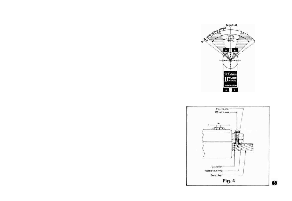
•Using dual travel
When the dual travel switch is set to ON, the steering angle can be
made small within the range of the hatched lines of Fig.3. The steer-
ing angle is variable within the range maximum, 90% of total oper-
ating angle, minimum 40%.
•The dual travel aileron switch should normally be set to OFF Set this
switch to ON when desiring to make the aileron steering angle small such
as slow roll, etc Then set the steering angle with the trimmer
*The dual travel elevator switch should normally be set to OFF But when
desiring a large steering angle such as spins, etc , set the switch to ON and
adjust the steering angle with the horn adjuster trimmer for level flight.
Kick-up will occur and the elevator steering angle will become large when
the switch is OFF
•The receiver channel order is shown in Fig-.5.
Since each lead wire of the connectors is color coded, connect the
servos in accordance with these colors. Attaching the accessory chan-
nel tabs is convenient.
Fig. 3