Futaba 5 User Manual
Page 6
vers. The auxiliary or 5 channel is not independently trimmable. Two
sets of control stick knob of d i f f e r e n t lengths are supplied with this
system, since i n d i v i d u a l preferences for control stick length may vary.
Stick knob may be interchanged by merely p u l l i n g the knob directly a-
way from the stick. The replacement knob should be pushed onto the
stick u n t i l it is fixed.
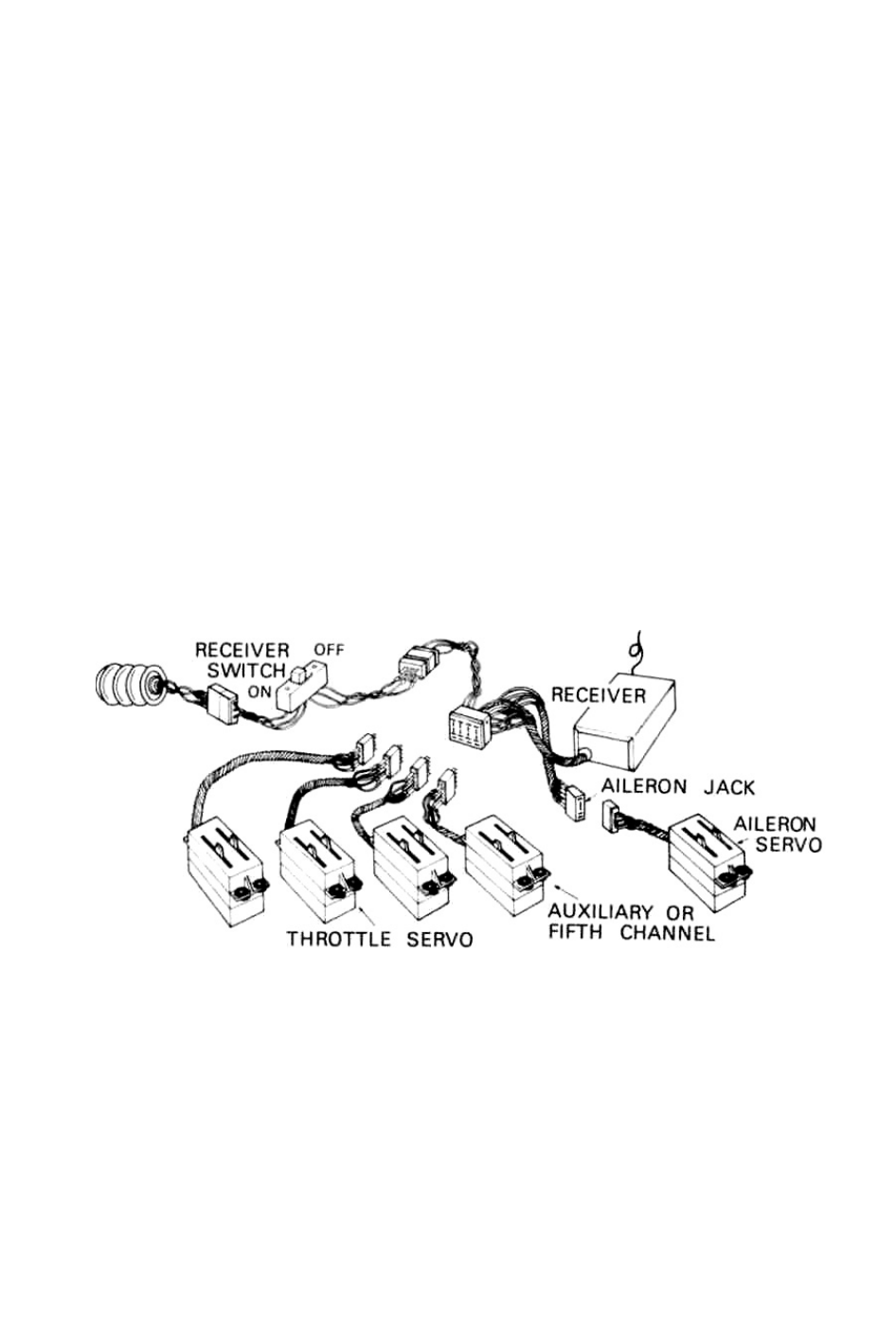
RECEIVER:
This receiver has been factory tuned and adjusted to the transmitter,
no further adjustments are requiredand the receiver should not be tam-
pered w i t h . Attach to the receiver is the antenna, one 7pin plug and
2 jacks. The seven pin plug connects the receiver battery pack and
supplies power to the receiver and servos. The multi connectors jack
is for the rudder, throttle, elevator and auxiliary the aileron servo.
See diagram below.
Note: Receiver connector has a white dot on one end. For auxiliary
(5th) channel, plug servo into this end of connector.
OPERATION CHECK:
1. Connect servo plugs to receiver jack, next connect receiver to bat-
tery pack.
2.Collapse transmitter antenna and turn the switch on. Next turn the
receiver switch on. A l l servos should stop at the neutral position.
3. Make sure that each of the servos operates correctly and responds to
the i n d i v i d u a l stick and trim lever. This test should be performed at
least 20 yards from the receiver. Don't test for longer than 5 minutes.
Futaba FP-T4 and FP-T5 are very high put type transmitters.