Check, test & start procedure, Warning – FloAire SIDD-FA User Manual
Page 3
Twin City IM 4205
3
Table 1. Wheel to Inlet Venturi
MODEL
OVERLAP
BSI
0.50
DSI
0.50
Check, Test & Start Procedure
WARNING
Electric shock hazard. Could cause severe injury or
death. Failure to bond the frame of this equipment
to the building electrical ground by use of the
grounding terminal provided or other acceptable
means may result in electrical shock. Disconnect
electric power before servicing equipment. Service
to be performed only by qualified personnel.
BEFORE START-UP: Disconnect power to this unit
before servicing the unit.
1. Check to verify that the wheel is free to rotate.
2. For optimum fan performance make sure that the
wheel to inlet venturi overlap is maintainted. See
Table 1.
3. Verify that supply voltage on the line side of discon-
nect agrees with voltage on fan data plate and is
within the 10% utilization voltage.
4. Apply power to unit and check rotation of wheel with
the directional arrow on the unit. See Table 2.
WARNING: Rotation is critical. If allowed to operate
in the wrong direction, the motor will overload and
burn out.
WARNING: Check units for rotation. For three-phase,
rotation can be changed by interchanging any two of
the three line leads. If unit is checked on temporary
wiring, it should be rechecked when permanently
installed. Motor burn-out or tripped overload protec-
tion devices are usually the result of wrong rotation.
5.
Electrical Input Check: Perform check of fan ampere
draw and verify that motor nameplate amps are not
exceeded. Take into account the service factor range
if motor is nameplated above a 1.0 service factor.
6. Fan RPM should be checked and verified with a
tachometer.
7.
Units with Speed Control (Direct Drive): Verify that
speed controller gives desired operating range of
RPM. If minimum speed value is not desired, it may
be adjusted. See page 4.
NOTE: The fan was balanced at the factory to be
within stringent vibration levels before shipment.
However, there are several things that may cause
vibration, such as rough handling in shipment and
installation, weak foundations and alignments.
Table 2. Wheel Rotation*
MODEL
CW
CCW
BSI
all
---
DSI
---
all
* Wheel rotation is determined when viewed from discharge.
Note: On fans with three phase motors the wheel rotation can
be changed by reversing any two power leads.
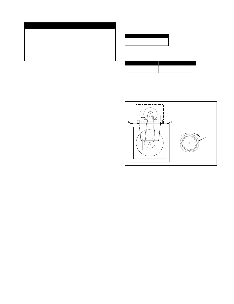
Figure 1. Fan Wheel Rotation - View from Discharge
WH
EEL
ROTATION
FAN
WHEEL
Note: CW rotation shown, CCW rotation is similar but opposite.