Flintec, The right weigh – Flintec LAC 74.1 User Manual
Page 3
Calibration of the analogue output
1. Mounting the module
The SG module has to be installed in a cabinet in compliance with (inter)national electrical
regulations. Connection details are printed on the upper face of the amplifier housing.
The amplifier module supports 6 wire technique. If you are using a 4 wire load cell, the
“Exc +” and “Sen +” terminals must be shorted together as well as the “Exc –“ and “Sen –“
terminals.
2. Adjustment settings
All DIP-switches and potentiometers are positioned near the top edge of the housing.
3. Setup DIP-switches
Zero setting:
The left six DIP-switches permit the off-set to be adjusted in steps of 0.5 mV throughout the
range of 0 to 31.5 mV. The seventh DIP-switch sets the polarity of the zero adjustment, either
Positive (ON) to make the output more positive or Negative (OFF) to make the output more
negative. The 20-turn potentiometer permits fine trimming of the zero point.
The total range is + or – 80%.
DIP-switch ON
none
1
2
3
4
5
6
all
Pol.
Pot.
Relative to 20 mV
%
0
2.5
5
10
20
40
80
157.5
+/–
3
Input at Zero V
out
mV
0
0.5
1
2
4
8
16
31.5
+/–
0.6
Span (Gain) setting:
The seven DIP-switches permit the relative gain to be set in 128 steps of 0.25x over the range
1 to 32. The 20-turn potentiometer permits fine trimming. Therefore, any input signal range
between 0.1 mV/V and 3.2 mV/V can be used to generate the full scale output (0 – 10 V or
0 – 20 mA or 4 – 20 mA). Note that the higher the gain, the lower the resolution that can be
obtained.
DIP-switch ON
none
1
2
3
4
5
6
7
all
Pot.
Relative gain factor
f
1
0.25
0.5
1
2
4
8
16
33
0.3
Input at 10V V
out
mV
32
30
28
24
16
8
4
2
1
xx
FLINTEC
...the right weigh
Manual LAC 74.1
Page 3
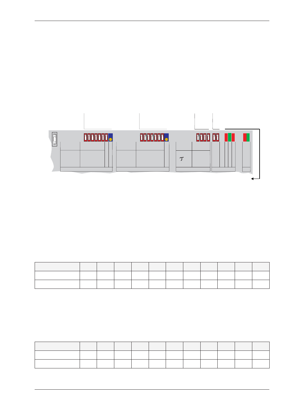
DIP-switches for choosing
analogue output
0-20 mA or 4-20 mA or 0-10 V.
33
10
3,3
1
0,33
OUTPUT
Error
Power
O
K
20mA
o.10V
0-20
o.
4-20mA
CND
5
16
50
160
500
SET
FILTER
f
CUT
ms
0,1
0,25
0,5
1,0
2,0
4,0
8,0
16,0
SET SPAN Pot ccw =calib.
Relative
gain*
Resolution
*1000n
Fine
adjust
60
50
40
30
20
13
7
4
0
0,5
1,0
2,0
4,0
8,0
16,0
SET ZERO Pot ccw =calib.
IN
% at
2mV/V
Fine
adjust
0
2,5
5
10
20
40
80
Pol.
+/-
mV
DIP-switches and
potentiometer
for zero setting
DIP-switches and
potentiometer
for gain setting
DIP-switches
for low pass filter
0.5-33 Hz
Under
In
range
Over
OFF
ON
Under
In range
Over
Error
Power OK
=
=
=
=
=
signal out of range (e.g. negative too)
input signal OK
signal out of range (e.g. > 2 mV/V)
error message safety logic
power is ON