Introduction and technical data, Mechanical installation, Electrical connections – Flintec KPK-4 User Manual
Page 3: Load cell cable connection
I
NTRODUCTION AND TECHNICAL
D
ATA
The Polyester junction box is designed for the parallel connection of load cells.
Type
No. of load cells
Housing size
Inputs
Output
KPK-4
up to 4
75 x 230 x 50 mm
4x M12
1x M16
The junction box type KPK can be connected to the instrumentation with a shielded 6-wire signal cable.
The corner correction is done with resistors and/or potentiometer.
Housing material:
Polyester
Protection class:
IP66
Cable connection:
With clamping terminals
Corner correction:
By exchangeable resistors and/or potentiometer
M
ECHANICAL
I
NSTALLATION
Look for a mounting location which is more or less dry and protected from environmental stress.
E
LECTRICAL
C
ONNECTIONS
1
2
2
1
1
2
2
1
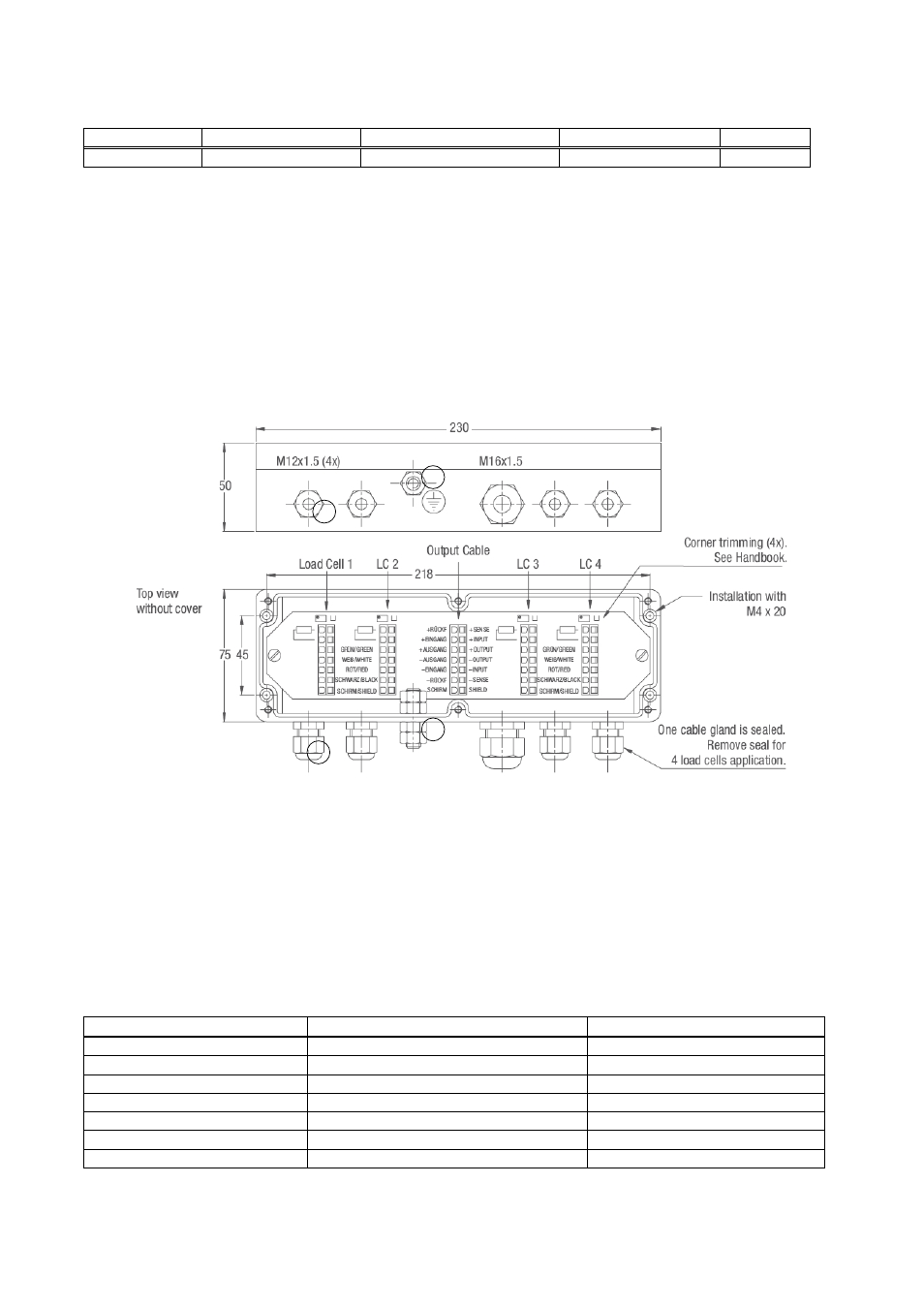
Figure 1: Dimensions in [mm]
The earth screw (see (2) in fig.1) has to be connected to protective earth or you must establish an electrical
connection to the weigh modules for potential equalisation.
The connection sequence of the load cells should correspond to the corners of the scale, i.e
Corner 1 = Load cell 1, Corner 2 = Load cell 2, etc.
L
OAD
C
ELL
C
ABLE
C
ONNECTION
First the cable gland (see (1) in fig.1) must be loosened. Then you have to feed the load cell cable through the
cable gland unless the shrink tube is fully disappeared in the box. The wires have to run below the printed
circuit board and will be pulled back to the top at the upper end of the printed circuit board. Afterwards you can
connect the cables to the clamping terminals as indicated below:
Cable coulour
Description
Terminal designation
yellow
= Cable shield
Shield / Schirm
red
= Signal – (Output –)
red / rot
white
= Signal + (Output +)
white /weiss
black
= Excitation – (Input –)
black / schwarz
(if applicable, brown)*
= Sense –
black / schwarz
green
= Excitation + (Input +)
green / grün
(if applicable, blue)*
= Sense +
green / grün
* if load cell is equiped with 6-wire conductor cable
After all conductors have been clamped to the terminals, the cable glands must be tightened. Please verify
that all cable glands are tight and the cable is fully stress relieved.
Junction Box Type KPK – Technical Manual, Rev. 1.01 June 2009
Page 3 of 4