Flintec KAL-4 User Manual
Page 3
Digital Junction Box Type KAL-4 – Technical Manual, Rev. 1.00 Dezember 2010
Page 3 of 4
I
NTRODUCTION AND TECHNICAL
D
ATA
The painted aluminium junction box KAL-4 is designed to connect up to 4 load cells in parallel. A socket on
the printed circuit board is prepared for accommodating one type LDU xx.x Load Cell Digitizing Unit.
Type
No. of load cells
Housing size
Inputs
Outputs
KAL-4
up to 4
80 x 250 x 52 mm
4x M16
3x M16
Housing material:
Aluminium
Protection class:
IP66
Cable connection:
With clamping terminals
Corner correction:
By exchangeable resistors
M
ECHANICAL
I
NSTALLATION
Look for a mounting location which is more or less dry and protected from environmental stress.
E
LECTRICAL
C
ONNECTIONS
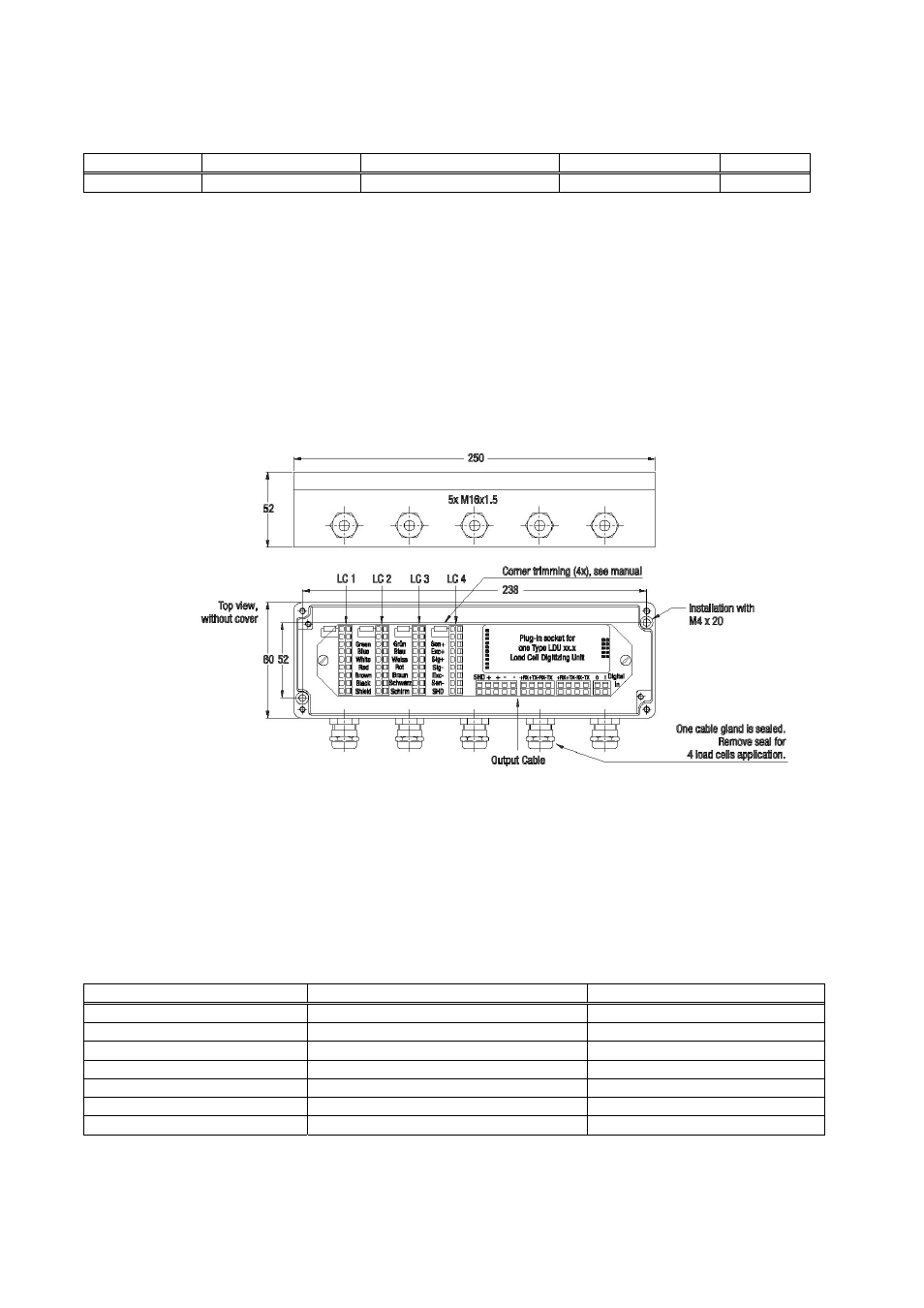
Figure 1: Dimensions in [mm]
The connection sequence of the load cells should correspond to the corners of the scale, i.e
Corner 1 = Load cell 1, Corner 2 = Load cell 2, etc.
L
OAD
C
ELL
C
ABLE
C
ONNECTION
First the cable gland (see in fig.1) must be loosened. Then you have to feed the load cell cable through the
cable gland unless the shrink tube is fully disappeared in the box. The wires have to run below the printed
circuit board and will be pulled back to the top at the upper end of the printed circuit board. Afterwards you can
connect the cables to the clamping terminals as indicated below:
Cable coulour
Description
Terminal designation
yellow
= Cable shield
Shield / Schirm
red
= Signal – (Output –)
red / rot
white
= Signal + (Output +)
white /weiss
black
= Excitation – (Input –)
black / schwarz
(if applicable, brown)*
= Sense –
black / schwarz
green
= Excitation + (Input +)
green / grün
(if applicable, blue)*
= Sense +
green / grün
* if load cell is equiped with 6-wire conductor cable
After all conductors have been clamped to the terminals, the cable glands must be tightened. Please verify
that all cable glands are tight and the cable is fully stress relieved.