Flintec – Flintec FRD-57 User Manual
Page 3
Remote Display FRD-57
Datum
Code
Rev
Seite
FLINTEC
27.09.04
FRD-57
3 von 3
Sample for Settings Indikator FT-01 / FT-02
.
Connection via RS-232 Interface
Connect the Tx and GND at the FT-Indicator with Tx and SGND at the remote
Indicator. The shield should conneted via the screwed cable gland (single-edge)
Please consider the max. cable length with RS-232 respectively TTY Interface
is 15 meters and with RS-485 max. 1000 meters should not exceed.
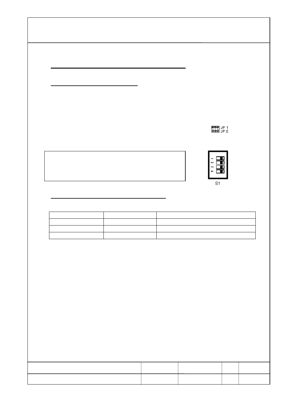
The Jumper JP1 and JP2 at the remote indicator must be
open .
The Dip switch S1 adjust as following :
1 = on ( 2400 Baud )
2 = off
3 = on ( non parity, 8 data bits, 1 Stop bit )
4 = off
Settings at Indicator FT-01 / FT-02 Setup 2
Setup 2 Parameter
Value
Description
2.t
02
cont. sending of weight value
2.7
0
control mode misprint off
2.d
08
8 Data- bits / nonparity