Tips for trouble shooting load cells and scales – Flintec LCT-11 User Manual
Page 2
LCT-11 Quick User Guide V.1.00, September 2012
Page 2 of 3
Tips for Trouble Shooting Load Cells and Scales
Load cells might be damaged due to many reasons: Overloading, overvoltage, moisture or chemical ingress,
vibrations, corrosion, pulling the cable etc. As a result a scale may provide unstable readings, zero drifting, error
reading, non-linearity etc.
The LCT-11 is the only measuring tool required to perform the tests either on site or in the lab. Before you start,
make sure to have the load cell specifications and the cable colour code available (usually you get the
information with the load cell, or you can find it on the internet: see
www.flintec.com
).
How to test a weighing platform with a few load cells:
1. Preparation: Leave all load cells connected to the junction box. Disconnect the cable from the weighing
indicator and connect it to the LCT-11.
2. Perform a test. The expected results for an error-free scale are as per the following example:
If the scale consists of 4 load cells (1 k
Ω
resistance and 100 kg capacity each) and 40 kg are applied as total
load (dead load + test weight), then you would expect to see around 250
Ω
for the input and the output (total
of the input respective output resistance divided by the number of load cells, here this is 4).
In case of 6-wire cables you should expect to get very low resistance values between the sense lines and the
input (according to the cable resistivity) as those wires are shorted inside the load cell. In this example the
signal output must be around 10% (total load cell capacity is 400 kg) and the insulation resistance (Body to
Bridge and Shield to Bridge) must remain very high, i.e. > 3 G
Ω
.
3. If some of the results are not in the required range, or you get erratic / unstable readings when testing in the
Continuous display mode: Check the junction box for moisture and dirt (leakage current?, leftover flux from
soldering?) Check the cable integrity between the junction box and the instrument. If everything looks fine,
disconnect each load cell cable and check each load cell separately.
Note: At the moment there is no need to remove the load cell from the scale.
4. If all results seem to be in the range, you may check the scale for linearity, by selecting Continuous display
mode on the LCT-11 and applying various test weights on the scale.
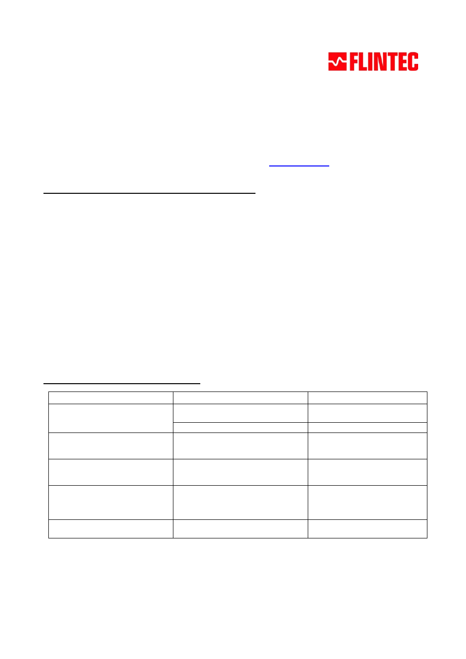
Understanding the LCT-11 Test results:
Test result with LCT-11
Possible reasons
What to do?
Input / Output resistance not in the
expected range
Cable or connector problem
Check the cable integrity and the
connectors
Problems inside the load cell
Replace the load cell
Sense is too high (6-wire load cell)
Excitation and Sense not connected
inside the load cell or 4-wire load cell was
tested as a 6-wire type
Replace the load cell
Signal output from the scale is not in
the expected range
Corrosion, force shunts, accumulated
dust below the load cell or a faulty load
cell, dirty or humid junction box
Clean the dust and check for force
shunts and alignment. Replace the
load cell if necessary
Signal output of the unloaded scale is
not in the expected range (target
value according to the scale’s dead
load)
One or more load cells are damaged due
to a mechanical shock or overload
Replace the load cells
Insulation resistance (Body to bridge /
Shield to bridge) is too low
Insulation error due to water or chemical
ingress to the cable or into the load cell
Replace the cable and / or the load
cell