Ordering information, Package diagrams – Cypress CY7C1353G User Manual
Page 12
CY7C1353G
Document #: 38-05515 Rev. *E
Page 12 of 13
© Cypress Semiconductor Corporation, 2004-2007. The information contained herein is subject to change without notice. Cypress Semiconductor Corporation assumes no responsibility for
the use of any circuitry other than circuitry embodied in a Cypress product. Nor does it convey or imply any license under patent or other rights. Cypress products are not warranted nor intended
to be used for medical, life support, life saving, critical control or safety applications, unless pursuant to an express written agreement with Cypress. Furthermore, Cypress does not authorize
its products for use as critical components in life-support systems where a malfunction or failure may reasonably be expected to result in significant injury to the user. The inclusion of Cypress
products in life-support systems application implies that the manufacturer assumes all risk of such use and in doing so indemnifies Cypress against all charges.
ZBT is a trademark of Integrated Device Technology, Inc. NoBL and No Bus Latency are trademarks of Cypress Semiconductor.
All product and company names mentioned in this document are the trademarks of their respective holders.
Ordering Information
Not all of the speed, package and temperature ranges are available. Please contact your local sales representative or
visit
www.cypress.com
for actual products offered.
Speed
(MHz)
Ordering Code
Package
Diagram
Part and Package Type
Operating
Range
133
CY7C1353G-133AXC
51-85050 100-Pin Thin Quad Flat Pack (14 x 20 x 1.4 mm) Pb-Free
Commercial
CY7C1353G-133AXI
lndustrial
100
CY7C1353G-100AXC
51-85050 100-Pin Thin Quad Flat Pack (14 x 20 x 1.4 mm) Pb-Free
Commercial
CY7C1353G-100AXI
lndustrial
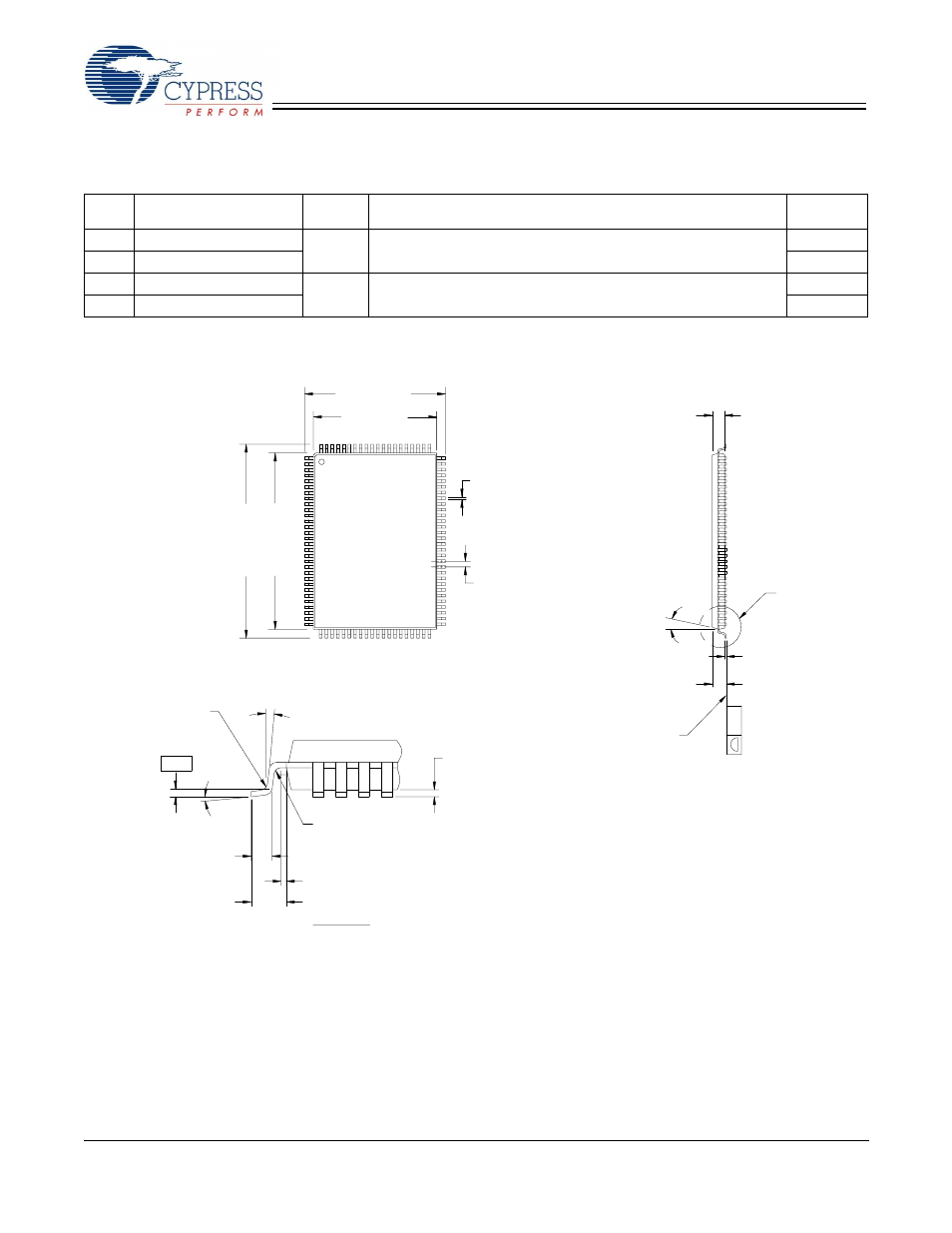
Package Diagrams
NOTE:
1. JEDEC STD REF MS-026
2. BODY LENGTH DIMENSION DOES NOT INCLUDE MOLD PROTRUSION/END FLASH
MOLD PROTRUSION/END FLASH SHALL NOT EXCEED 0.0098 in (0.25 mm) PER SIDE
3. DIMENSIONS IN MILLIMETERS
BODY LENGTH DIMENSIONS ARE MAX PLASTIC BODY SIZE INCLUDING MOLD MISMATCH
0.30±0.08
0.65
20.00±0.10
22.00±0.20
1.40±0.05
12°±1°
1.60 MAX.
0.05 MIN.
0.60±0.15
0° MIN.
0.25
0°-7°
(8X)
STAND-OFF
R 0.08 MIN.
TYP.
0.20 MAX.
0.15 MAX.
0.20 MAX.
R 0.08 MIN.
0.20 MAX.
14.00±0.10
16.00±0.20
0.10
SEE DETAIL
A
DETAIL
A
1
100
30
31
50
51
80
81
GAUGE PLANE
1.00 REF.
0.20 MIN.
SEATING PLANE
100-Pin TQFP (14 x 20 x 1.4 mm) (51-85050)
51-85050-*B