Mac 10, Vcu control – Envirco MAC 10 VCU User Manual
Page 2
MAC 10
®
VCU Control
Operation Guide
W i r i n g D e t a i l s & O p e r a t i o n
■
VCU Operation
The fan filter unit needs to be turned on prior to operation of the control. With the
Visual Speed Control board, a single screw driver is required to adjust the unit airflow.
Just to the left of the LED readout is a recessed blue slotted stem which when turned
clockwise will increase the airflow and if turned counter clockwise will decrease the
airflow. The LED readout alternates between outputting the selected flow index (%)
and the actual motor RPM.
■
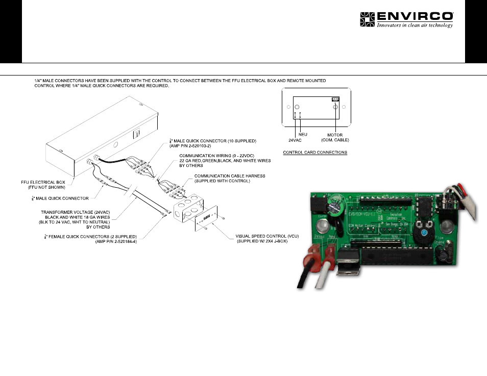
Wiring Detail
Please make sure all power is off before making these connections.
• The six leads exiting the FFU electrical box have ¼” female quick connectors.
• The leads attached to the control have ¼” female quick connectors.
• Please follow all applicable local codes for low voltage wiring. Conduit or plenum
rated cables may be required.
• The wiring between the FFU electrical box and the controls require the 18 gauge
black and white leads (24VAC) be connected to the same 18 gauge wire colors on
the control (white to white and black to black).
• The 22 gauge communication wiring (0-22VDC) is also color coded. Connect the
red wire out of the electrical box to the red wire on the remote mounted control.
Connect the green wire to the green wire; the black wire to the black wire and the
white wire to the white wire.
• 1/4” male connectors have been supplied with the control to connect between the
FFU electrical box and remote mounted control where 1/4” male quick connectors
are required.
MAC 10 LEDC and IQ VCU controls
for remote mount part number 11166-001