Operating instructions – ebm-papst W6D710-GH01-01 User Manual
Page 5
Operating instructions
W6D710-GH01-01
Translation of the original operating instructions
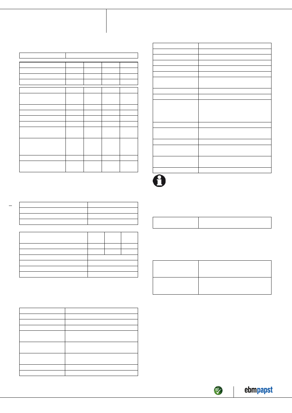
3.2 Nominal data
Motor
M6D138-HF
Phase
3~
3~
3~
3~
Nominal voltage / VAC
400
400
480
480
Connection
Δ
Y
Δ
Y
Frequency / Hz
50
50
60
60
Type of data definition
ml
ml
ml
ml
Valid for approval /
standard
CE
CE
CE
CE
Speed / min
-1
905
730
1060
780
Power input / W
1030
690
1700
1030
Current draw / A
2.35
1.34
2.87
1.72
Max. back pressure / Pa
125
80
170
92
Min. ambient temperature
/ °C
-40
-40
-40
-40
Max. ambient
temperature
/ °C
80
80
60
60
Starting current / A
9
3
10
3.5
Maximum safe operating
speed / min
-1
1650
@ 70 °C
1650
@ 70 °C
1650
@ 70 °C
1650
@ 70 °C
ml = Max. load · me = Max. efficiency · fa = Running at free air
cs = Customer specs · cu = Customer unit
Subject to alterations
3.3 Data according to ErP directive
Installation category
A
Efficiency category
Static
Variable speed drive
No
Specific ratio
*
1.00
*
Specific ratio = 1 + p
fs
/ 100 000 Pa
Actual
Request
2013
Request
2015
Overall efficiency η
es
/ %
33.6
29.6
33.6
Efficiency grade N
40
36
40
Power input P
e
/ kW
0.97
Air flow q
v
/ m³/h
10730
Pressure increase total p
sf
/ Pa
111
Speed n / min
-1
910
Data definition with optimum efficiency.
The ErP data is determined using a motor-impeller combination in a standardised
measurement configuration.
3.4 Technical features
Mass
37.2 kg
Size
710 mm
Surface of rotor
Cast in aluminium
Material of terminal box
Plastic, fibreglass-reinforced
Material of blades
Aluminium sheet insert, sprayed with PP
plastic
Material of wall ring
Sheet steel, pre-galvanised and coated
with black plastic
Material of guard grille
Steel, phosphated and coated in black
plastic
Number of blades
5
Blade angle
-5°
Direction of air flow
"V"
Direction of rotation
Clockwise, seen on rotor
Type of protection
IP 54
Insulation class
"F"
Humidity class
F3-1
Mounting position
Any
Condensate discharge
holes
On rotor and stator sides
Operation mode
S1
Motor bearing
Ball bearing
Touch current acc.
IEC 60990 (measuring
network Fig. 4, TN
system)
<= 3.5 mA
Electrical leads
Via terminal box
Motor protection
Thermal overload protector (TOP)
brought out
Cable exit
Axial
Protection class
I (if protective earth is connected by
customer)
Product conforming
to standard
EN 61800-5-1; EN 60034; CE
Approval
EAC; VDE
For cyclic speed loads, note that the rotating parts of the device
are designed for maximum one million load cycles. If you have
specific questions, contact ebm-papst for support.
3.5 Mounting data
; Secure the mounting screws against accidentally coming loose (e.g.
by using self-locking screws).
Strength class for
mounting screws
8.8
You can obtain additional mounting data from the product drawing if
necessary.
3.6 Transport and storage conditions
; Use the device in accordance with its protection type.
Max. permissible
ambient motor temp.
(transp./ storage)
+ 80 °C
Min. permissible
ambient motor temp.
(transp./storage)
- 40 °C
Item no. 10698-5-9970 · Revision 82513 · Release 2014-06-10 · Page 5 / 10
ebm-papst Mulfingen GmbH & Co. KG · Bachmühle 2 · D-74673 Mulfingen · Phone +49 (0) 7938 81-0 · Fax +49 (0) 7938 81-110 · [email protected] · www.ebmpapst.com