Operating instructions – ebm-papst W3G910-GU31-11 User Manual
Page 7
Operating instructions
W3G910-GU31-11
Translation of the original operating instructions
→ Ensure a sufficiently large clearance.
Recommendation: clearance > 10 cm (separate cable
routing)
NOTE
Water penetration into leads or wires
Water enters at the cable end on the customers side and can
damage the device.
→ Make sure that the cable end is connected in a dry
environment.
Connect the device only to circuits that can be switched off
using an all-pole disconnecting switch.
4.2.1 Prerequisites
; Check whether the data on the type plate agree with the connection
data.
; Before connecting the device, ensure that the supply voltage matches
the operating voltage of the device.
; Only use cables designed for current according to the type plate.
For determining the cross-section, follow the basic principles in
accordance with EN 61800-5-1. The protective earth must have a
cross-section equal to or greater than the outer conductor cross-
section.
We recommend the use of 105°C cables. Ensure that the minimum
cable cross-section is at least
AWG26/0.13 mm².
Earth wire contact resistance to EN 61800-5-1
Compliance with the impedance specifications to EN 61800-5-1 for the
protective earth circuit must be verified in the end application.
Depending on the installation situation, it may be necessary to install an
additional protective earthing conductor via the additional protective earth
connection point available on the device.
The protective earth connection point is located on the housing and has
a protective earth symbol and a bore hole.
4.2.2 Power supply connection, fuse protection
Assignment of conductor cross-sections and the fuse protection required
for them (overload protection only, no device protection).
Nominal
voltage
Safety fuse
Wire cross-
section
Wire cross-
section
UL
mm²
AWG
3/PE AC 200-
240 VAC
15 A
1.5
16
3/PE AC 200-
240 VAC
20 A
2.5
14
3/PE AC 200-
240 VAC
30 A
4
12
* AWG = American Wire Gauge
4.2.3 Idle current
Because of the EMC filter integrated for compliance with EMC
limits (interference emission and interference immunity), idle
currents in the mains cable can be measured even when the
motor is at a standstill and the mains voltage is switched on.
●
The values lie in a range of typical < 250 mA.
●
The effective power in this operating state (readiness for operation) is
simultaneously at typical < 5 W.
4.2.4 Residual current operated device
Only universal (type B or B+) RCD protective devices are
permitted. Like frequency inverters, RCD protective devices
cannot provide personal safety while operating the device.
When switching on the power supply of the device, pulsed
charge currents from the capacitors in the integrated EMC filter
can lead to the RCD protective devices triggering without
delay. We recommend residual current devices with a trigger
threshold of 300 mA and delayed triggering (super-resistant,
characteristic K).
4.2.5 Leakage current
For asymmetrical power systems or if a phase fails, the
leakage current can increase to a multiple of the nominal value.
4.2.6 Locked-rotor protection
Due to the locked-rotor protection, the start-up current (LRA) is
equal to or less than the nominal current (FLA).
4.3 Connection via plug
4.3.1 Establish supply connections
; Check the PIN assignment of your connector.
; Connect the panel connector and mating connector.
; Ensure that the connector is locked in correctly.
4.3.2 Cable routing
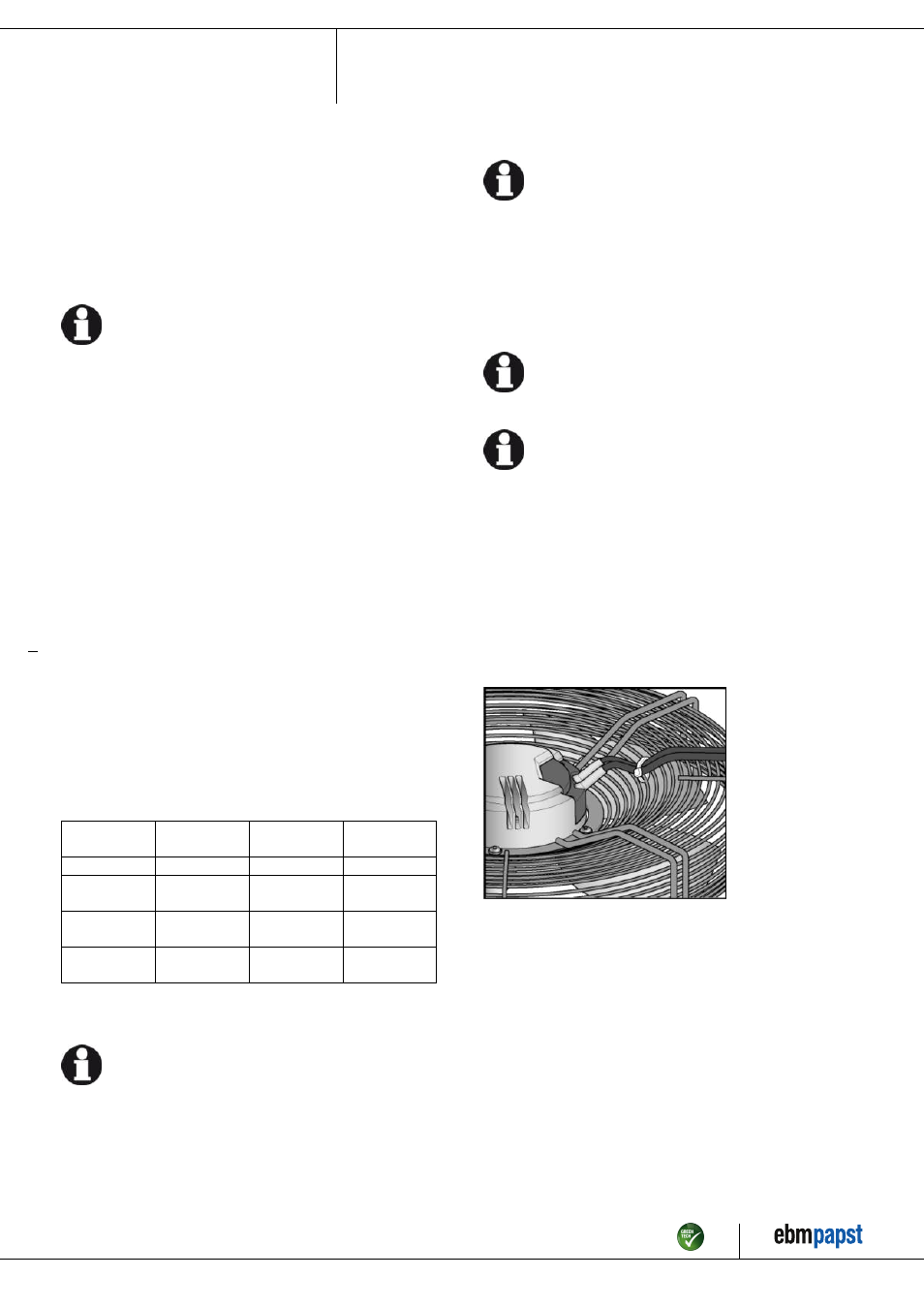
No water may penetrate along the cable in the direction of the cable exit.
Fans installed lying flat
Fig. 1: Fan installed lying flat, cable routed as a water trap.
Fans installed in upright position
Item no. 51801-5-9970 · ENG · Revision 83184 · Release 2014-10-23 · Page 7 / 12
ebm-papst Mulfingen GmbH & Co. KG · Bachmühle 2 · D-74673 Mulfingen · Phone +49 (0) 7938 81-0 · Fax +49 (0) 7938 81-110 · [email protected] · www.ebmpapst.com