Operating instructions – ebm-papst W3G710-GU30-11 User Manual
Page 5
Operating instructions
W3G710-GU30-11
Translation of the original operating instructions
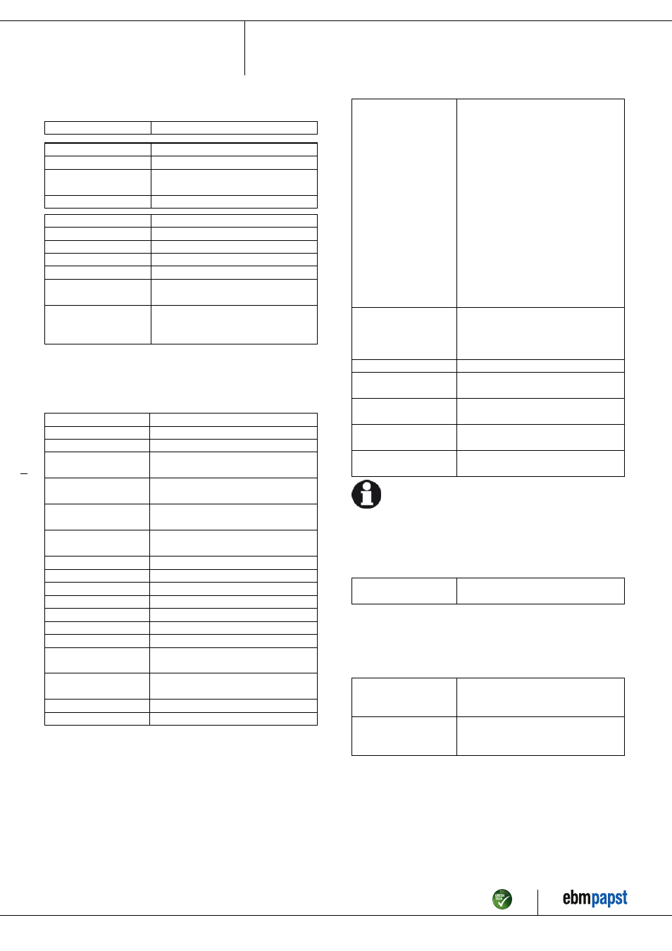
3.2 Nominal data
Motor
M3G150-IF
Phase
3~
Nominal voltage / VAC
200
Nominal voltage
range / VAC
200 .. 240
Frequency / Hz
50/60
Type of data definition
ml
Speed / min
-1
1230
Power input / W
2815
Current draw / A
8.8
Max. back pressure / Pa
240
Min. ambient temperature
/ °C
-25
Max. ambient
temperature
/ °C
60
ml = Max. load · me = Max. efficiency · fa = Running at free air
cs = Customer specs · cu = Customer unit
Subject to alterations
3.3 Technical features
Mass
42.5 kg
Size
710 mm
Surface of rotor
Coated in black
Material of electronics
housing
Die-cast aluminium, coated in black
Material of blades
Aluminium sheet insert, sprayed with PP
plastic
Material of wall ring
Sheet steel, pre-galvanised and coated in
black plastic
Material of guard grille
Steel, phosphated and coated in black
plastic
Number of blades
5
Blade angle
0°
Direction of air flow
"V"
Direction of rotation
Clockwise, seen on rotor
Type of protection
IP 54
Insulation class
"F"
Humidity class
F4-1
Mounting position
Shaft horizontal or rotor on bottom; rotor
on top on request
Condensate discharge
holes
Rotor-side
Operation mode
S1
Motor bearing
Ball bearing
Technical features
- External 24 V input (programming)
- RS485 MODBUS RTU
- PFC, passive
- Control input 0-10 VDC / PWM
- Over-temperature protected
electronics / motor
- Alarm relay
- Integrated PID controller
- Input for sensor 0-10 V or 4-20 mA
- Output for slave 0-10 V
- Motor current limit
- Soft start
- Line undervoltage / phase failure
detection
- Output 10 VDC, max. 10 mA
- Output 20 VDC, max. 50 mA
Touch current acc.
IEC 60990 (measuring
network Fig. 4, TN
system)
<= 3.5 mA
Electrical leads
Via terminal box
Motor protection
Reverse polarity and locked-rotor
protection
Protection class
I (if protective earth is connected by
customer)
Product conforming
to standard
EN 61800-5-1; CE
Approval
C22.2 Nr.77 + CAN/CSA-E60730-1;
EAC; UL 1004-7 + 60730
For cyclic speed loads, note that the rotating parts of the device
are designed for maximum one million load cycles. If you have
specific questions, contact ebm-papst for support.
3.4 Mounting data
; Secure the mounting screws against accidentally coming loose (e.g.
by using self-locking screws).
Strength class for
mounting screws
8.8
You can obtain additional mounting data from the product drawing if
necessary.
3.5 Transport and storage conditions
; Use the device in accordance with its protection type.
Max. permissible
ambient motor temp.
(transp./ storage)
+ 80 °C
Min. permissible
ambient motor temp.
(transp./storage)
- 40 °C
Item no. 50923-5-9970 · Revision 82539 · Release 2014-05-08 · Page 5 / 12
ebm-papst Mulfingen GmbH & Co. KG · Bachmühle 2 · D-74673 Mulfingen · Phone +49 (0) 7938 81-0 · Fax +49 (0) 7938 81-110 · [email protected] · www.ebmpapst.com