Operating instructions – ebm-papst A4D560-AR03-03 User Manual
Page 5
Operating instructions
A4D560-AR03-03
Translation of the original operating instructions
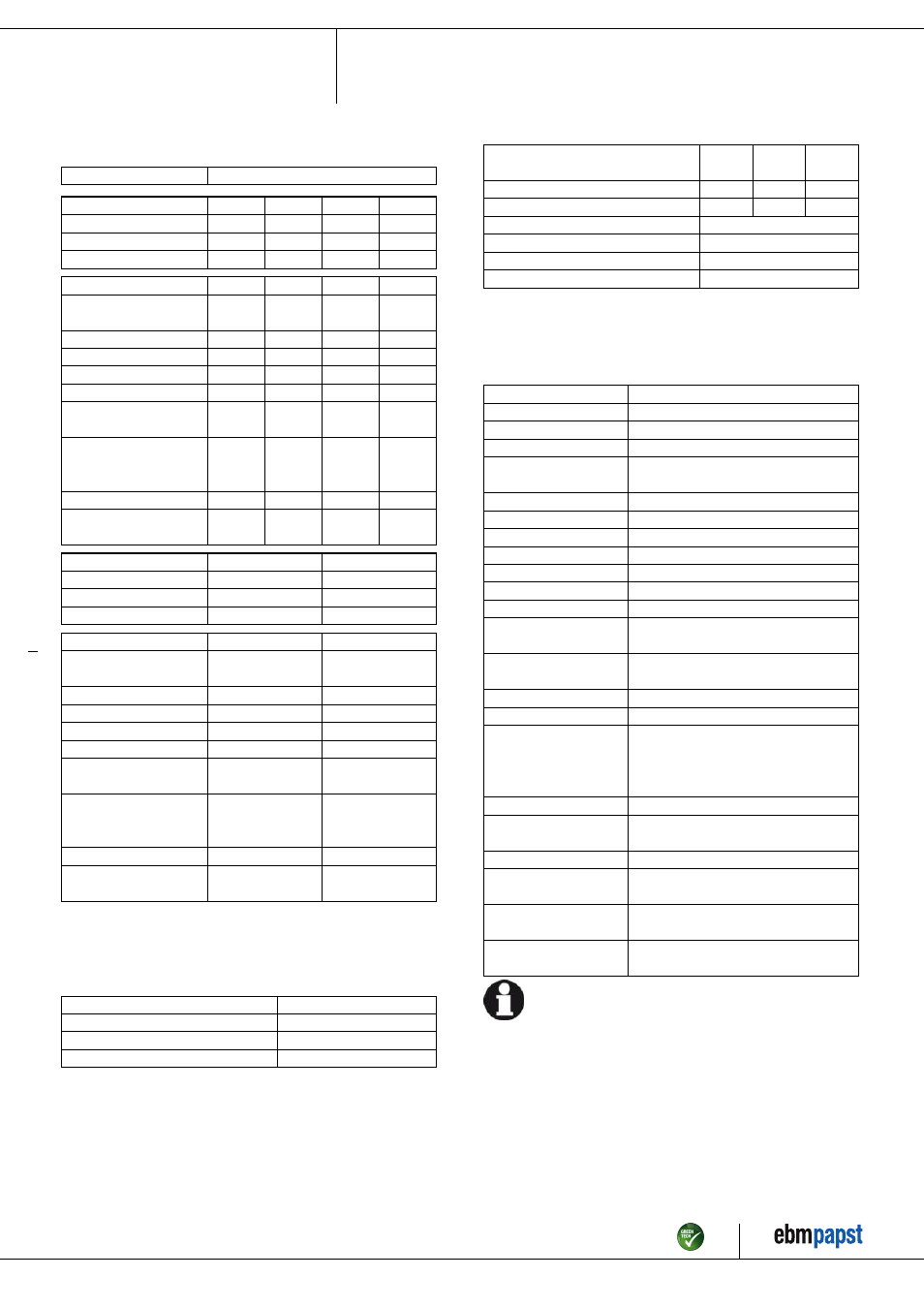
3.2 Nominal data
Motor
M4D110-IA
Phase
3~
3~
3~
3~
Nominal voltage / VAC
230
230
277
400
Connection
Δ
Δ
Δ
Y
Frequency / Hz
50
60
60
50
Type of data definition
ml
ml
ml
ml
Valid for approval /
standard
CE
CE
CE
CE
Speed / min
-1
1390
1575
1640
1390
Power input / W
880
1320
1420
880
Current draw / A
3.72
4.26
4.39
2.15
Max. back pressure / Pa
170
215
230
170
Min. ambient temperature
/ °C
-40
-40
-40
-40
Max. ambient
temperature
/ °C
65
65
65
65
Starting current / A
17
15
19
10
Maximum safe operating
speed / min
-1
1650
@ 70 °C
1650
@ 70 °C
1650
@ 70 °C
1650
@ 70 °C
Phase
3~
3~
Nominal voltage / VAC
400
480
Connection
Y
Y
Frequency / Hz
60
60
Type of data definition
ml
ml
Valid for approval /
standard
CE
CE
Speed / min
-1
1575
1640
Power input / W
1320
1420
Current draw / A
2.46
2.54
Max. back pressure / Pa
215
230
Min. ambient temperature
/ °C
-40
-40
Max. ambient
temperature
/ °C
65
65
Starting current / A
8.9
11.2
Maximum safe operating
speed / min
-1
1650
@ 70 °C
1650
@ 70 °C
ml = Max. load · me = Max. efficiency · fa = Running at free air
cs = Customer specs · cu = Customer unit
Subject to alterations
3.3 Data according to ErP directive
Installation category
A
Efficiency category
Static
Variable speed drive
No
Specific ratio
*
1.00
*
Specific ratio = 1 + p
fs
/ 100 000 Pa
Actual
Request
2013
Request
2015
Overall efficiency η
es
/ %
36.1
29.3
33.3
Efficiency grade N
42.8
36
40
Power input P
e
/ kW
0.87
Air flow q
v
/ m³/h
6755
Pressure increase total p
sf
/ Pa
169
Speed n / min
-1
1390
Data definition with optimum efficiency.
The ErP data is determined using a motor-impeller combination in a standardised
measurement configuration.
3.4 Technical features
Mass
12.1 kg
Size
560 mm
Surface of rotor
Cast in aluminium
Material of terminal box
PC / ABS plastic
Material of blades
Aluminium sheet insert, sprayed with PP
plastic
Number of blades
5
Blade angle
-10°
Direction of air flow
"V"
Direction of rotation
Counter-clockwise, seen on rotor
Type of protection
IP 54
Insulation class
"F"
Humidity class
F3-1
Mounting position
Shaft horizontal or rotor on bottom; rotor
on top on request
Condensate discharge
holes
Rotor-side
Operation mode
S1
Motor bearing
Ball bearing
Touch current acc.
IEC 60990 (measuring
network Fig. 4, TN
system)
<= 3.5 mA
Electrical leads
Via terminal box
Motor protection
Thermal overload protector (TOP)
brought out
Cable exit
Axial
Protection class
I (if protective earth is connected by
customer)
Product conforming
to standard
EN 61800-5-1; CE
Approval
CSA C22.2 Nr.100; EAC; UL 1004-1;
VDE
For cyclic speed loads, note that the rotating parts of the device
are designed for maximum one million load cycles. If you have
specific questions, contact ebm-papst for support.
Item no. 10611-5-9970 · Revision 82543 · Release 2014-05-08 · Page 5 / 11
ebm-papst Mulfingen GmbH & Co. KG · Bachmühle 2 · D-74673 Mulfingen · Phone +49 (0) 7938 81-0 · Fax +49 (0) 7938 81-110 · [email protected] · www.ebmpapst.com