Operating instructions – ebm-papst A3G630-AD03-A8 User Manual
Page 7
Operating instructions
A3G630-AD03-A8
Translation of the original operating instructions
We recommend the use of 105°C cables. Ensure that the minimum
cable cross-section is at least
AWG26/0.13 mm².
Earth wire contact resistance to EN 61800-5-1
Compliance with the impedance specifications to EN 61800-5-1 for the
protective earth circuit must be verified in the end application.
Depending on the installation situation, it may be necessary to install an
additional protective earthing conductor via the additional protective earth
connection point available on the device.
The protective earth connection point is located on the housing and has
a protective earth symbol and a bore hole.
4.2.2 Idle current
Because of the EMC filter integrated for compliance with EMC
limits (interference emission and interference immunity), idle
currents in the mains cable can be measured even when the
motor is at a standstill and the mains voltage is switched on.
●
The values lie in a range of typical < 250 mA.
●
The effective power in this operating state (readiness for operation) is
simultaneously at typical < 4 W.
4.2.3 Residual current operated device
Only universal (type B or B+) RCD protective devices are
permitted. Like frequency inverters, RCD protective devices
cannot provide personal safety while operating the device.
When switching on the power supply of the device, pulsed
charge currents from the capacitors in the integrated EMC filter
can lead to the RCD protective devices triggering without
delay. We recommend residual current devices with a trigger
threshold of 300 mA and delayed triggering (super-resistant,
characteristic K).
4.2.4 Locked-rotor protection
Due to the locked-rotor protection, the start-up current (LRA) is
equal to or less than the nominal current (FLA).
4.3 Connection in terminal box
4.3.1 Preparing connection lines for the connection
Strip the cable just enough so that the screwed cable gland is tight and
the terminals are relieved of strain. Tightening torque, see chapter 3.1
Product drawing.
4.3.2 Connecting cables with terminals
WARNING
Terminals and connections have voltage even with a
unit that is shut off
Electric shock
→ Wait five minutes after disconnecting the voltage at all poles
before opening the device.
; Remove the cap from the screwed cable gland.
Remove the cap only in those places where cables are inserted.
; Insert the line(s) (not included in the standard scope of delivery) into
the terminal box.
; Connect the lines to the corresponding terminals.
Use a screwdriver to do so.
During the connection work, ensure that no cables splice off.
; Seal the terminal box.
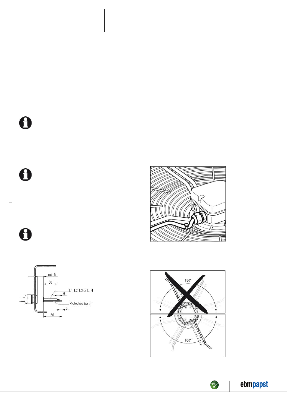
4.3.3 Cable routing
No water may penetrate along the cable in the direction of the cable gland.
Fans installed lying flat
Make sure that the cable is routed in the form of a loop (water trap).
Fig. 2: Fan installed lying flat, cable routed as a water trap.
Fans installed in upright position
When routing the cable, ensure that the screwed cable glands are
arranged at the bottom. The cables must always be routed downwards.
Fig. 3: Cable routing for fans installed upright.
Item no. 50611-5-9970 · Revision 82624 · Release 2014-05-08 · Page 7 / 12
ebm-papst Mulfingen GmbH & Co. KG · Bachmühle 2 · D-74673 Mulfingen · Phone +49 (0) 7938 81-0 · Fax +49 (0) 7938 81-110 · [email protected] · www.ebmpapst.com