Operating instructions – ebm-papst A3G300-AN02-03 User Manual
Page 5
Operating instructions
A3G300-AN02-03
Translation of the original operating instructions
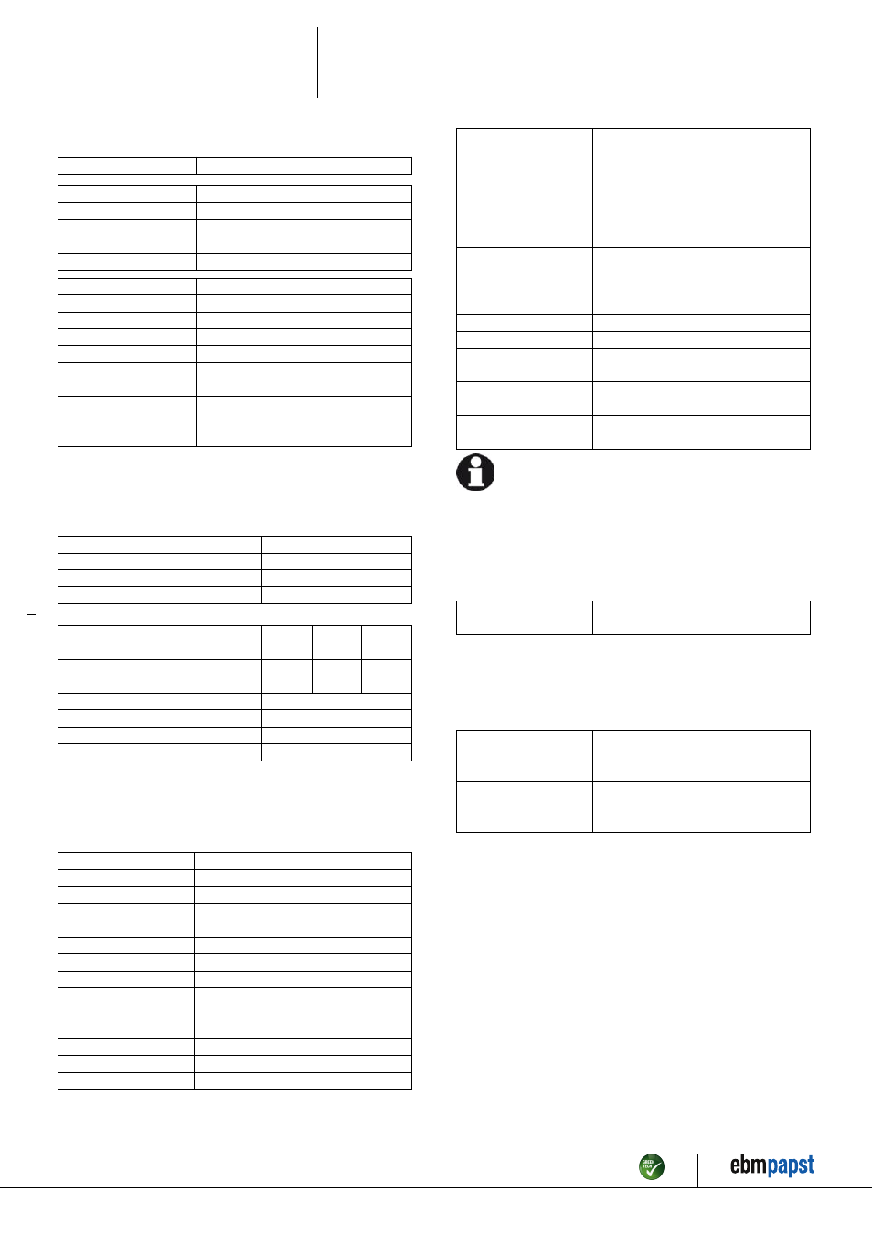
3.2 Nominal data
Motor
M3G074-CF
Phase
1~
Nominal voltage / VAC
230
Nominal voltage
range / VAC
200 .. 240
Frequency / Hz
50/60
Type of data definition
ml
Speed / min
-1
2020
Power input / W
170
Current draw / A
1.35
Max. back pressure / Pa
140
Min. ambient temperature
/ °C
-25
Max. ambient
temperature
/ °C
60
ml = Max. load · me = Max. efficiency · fa = Running at free air
cs = Customer specs · cu = Customer unit
Subject to alterations
3.3 Data according to ErP directive
Installation category
A
Efficiency category
Static
Variable speed drive
Yes
Specific ratio
*
1.00
*
Specific ratio = 1 + p
fs
/ 100 000 Pa
Actual
Request
2013
Request
2015
Overall efficiency η
es
/ %
43.1
24.6
28.6
Efficiency grade N
54.5
36
40
Power input P
ed
/ kW
0.16
Air flow q
v
/ m³/h
1795
Pressure increase total p
sf
/ Pa
128
Speed n / min
-1
2060
Data definition with optimum efficiency.
The ErP data is determined using a motor-impeller combination in a standardised
measurement configuration.
3.4 Technical features
Size
300 mm
Material of impeller
PP plastic
Number of blades
5
Direction of air flow
"V"
Direction of rotation
Counter-clockwise, seen on rotor
Type of protection
IP 54
Insulation class
"B"
Humidity class
F3-1
Mounting position
Any
Condensate discharge
holes
None, open rotor
Cooling bore / aperture
Rotor-side
Operation mode
S1
Motor bearing
Ball bearing
Technical features
- Output 10 VDC, max. 1.1 mA
- Tach output
- Motor current limit
- Soft start
- Control input 0-10 VDC / PWM
- Over-temperature protected
electronics / motor
Touch current acc.
IEC 60990 (measuring
network Fig. 4, TN
system)
<= 3.5 mA
Motor protection
PTC resistor
Cable exit
Variable
Protection class
I (if protective earth is connected by
customer)
Product conforming
to standard
CE
Approval
CCC; C22.2 Nr.77 + CAN/CSA-
E60730-1; UL 1004-7 + 60730
For cyclic speed loads, note that the rotating parts of the device
are designed for maximum one million load cycles. If you have
specific questions, contact ebm-papst for support.
3.5 Mounting data
For depth of screw, see chapter 3.1 Product drawing
; Secure the mounting screws against accidentally coming loose (e.g.
by using self-locking screws).
Strength class for
mounting screws
8.8
You can obtain additional mounting data from the product drawing if
necessary.
3.6 Transport and storage conditions
; Use the device in accordance with its protection type.
Max. permissible
ambient motor temp.
(transp./ storage)
+ 80 °C
Min. permissible
ambient motor temp.
(transp./storage)
- 40 °C
Item no. 51536-5-9970 · ENG · Revision 84194 · Release 2015-01-09 · Page 5 / 10
ebm-papst Mulfingen GmbH & Co. KG · Bachmühle 2 · D-74673 Mulfingen · Phone +49 (0) 7938 81-0 · Fax +49 (0) 7938 81-110 · [email protected] · www.ebmpapst.com