Operating instructions – ebm-papst M3G084-GF06-42 User Manual
Page 5
Operating instructions
M3G084-GF06-42
Translation of the original operating instructions
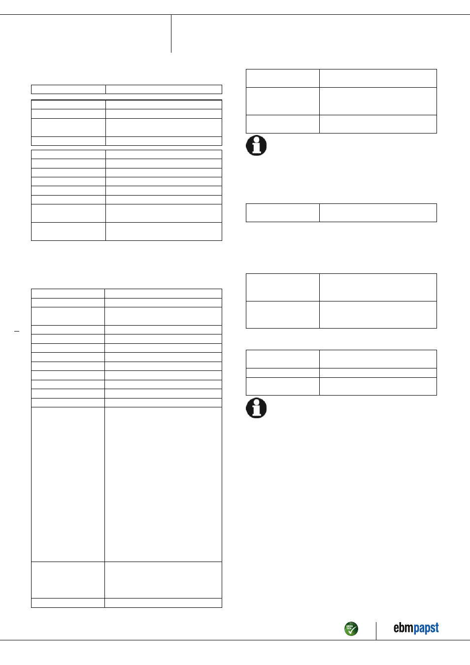
3.2 Nominal data
Motor
M3G084-GF
Phase
3~
Nominal voltage / VAC
400
Nominal voltage
range / VAC
380 .. 480
Frequency / Hz
50/60
Type of data definition
ml
Speed / min
-1
3000
Power input / W
750
Power output / W
630
Current draw / A
1.4
Rated torque / Ncm
200
Min. ambient
temperature / °C
-25
Max. ambient
temperature / °C
40
ml = max. load · me = max. efficiency · fa = running at free air
cs = customer specs · cu = customer unit
Subject to alterations
3.3 Technical features
Mass
7.7 kg
Size
84 mm
Material of electronics
housing
Die-cast aluminium
Housing material
Die-cast aluminium
Direction of rotation
Counter-clockwise, seen on shaft
Type of protection
IP 55
Insulation class
"B"
Humidity class
F3-1
Mounting position
Any
Cooling bore / aperture
Rotor-side
Operation mode
S1
Motor bearing
Ball bearing
Technical features
- Output 10 VDC, max. 10 mA
- Output 20 VDC, max. 50 mA
- Output for slave 0-10 V
- Input for sensor 0-10 V or 4-20 mA
- Alarm relay
- Integrated PID controller
- Motor current limit
- PFC, passive
- RS485 ebmBUS
- Soft start
- Control input 0-10 VDC / PWM
- Control interface with SELV potential
safely disconnected from the mains
- Over-temperature protected
electronics / motor
- Line undervoltage / phase failure
detection
Touch current acc.
IEC 60990 (measuring
network Fig. 4, TN
system)
<= 3.5 mA
Electrical leads
Via terminal box
Motor protection
Thermal overload protector (TOP) wired
internally
Protection class
I (if protective earth is connected by
customer at the connection point of the
housing)
Product conforming
to standard
EN 61800-5-1; CE
For cyclic speed loads, note that the rotating parts of the device
are designed for maximum one million load cycles. If you have
specific questions, contact ebm-papst for support.
3.4 Mounting data
; Secure the mounting screws against accidentally coming loose (e.g.
by using self-locking screws).
Strength class for
mounting screws
8.8
You can obtain additional mounting data from the product drawing if
necessary.
3.5 Transport and storage conditions
; Use the device in accordance with its protection type.
Max. permissible
ambient motor temp.
(transp./ storage)
+ 80 °C
Min. permissible
ambient motor temp.
(transp./storage)
- 40 °C
3.6 Electromagnetic compatibility
EMC interference
immunity
Acc. to EN 61000-6-2 (industrial
environment)
EMC harmonics
Acc. to EN 61000-3-2/3
EMC interference
emission
Acc. to EN 61000-6-3 (household
environment)
If several devices are switched in parallel on the mains side so
that the line current of the arrangement is in the range of 16 - 75
A, then this arrangement conforms to IEC 61000-3-12 provided
that the short-circuit power S
sc
at the connection point of the
customer system to the public power system is greater than or
equal to 120 times the rated output of the arrangement.
It is the responsibility of the installation engineer or operator/
owner of the device to ensure, if necessary after consultation
with the network operator, that this device is only connected to
a connection point with a S
sc
value that is greater than or equal
to 120 times the rated output of the arrangement.
Item no. 50852-5-9970 · Revision 79220 · Release 2013-01-08 · Page 5 / 12
ebm-papst Mulfingen GmbH & Co. KG · Bachmühle 2 · D-74673 Mulfingen · Phone +49 (0) 7938 81-0 · Fax +49 (0) 7938 81-110 · [email protected] · www.ebmpapst.com