Operating instructions – ebm-papst K3G250-RE09-05 User Manual
Page 5
Operating instructions
K3G250-RE09-05
Translation of the original operating instructions
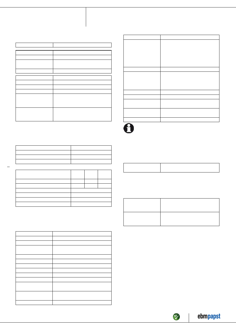
3.2 Nominal data
Motor
M3G055-DF
Phase
1~
Nominal voltage / VAC
230
Nominal voltage
range / VAC
200 .. 240
Frequency / Hz
50/60
Type of data definition
ml
Speed / min
-1
2510
Power input / W
170
Current draw / A
1.4
Min. ambient
temperature
/ °C
-25
Max. ambient
temperature
/ °C
60
ml = Max. load · me = Max. efficiency · fa = Running at free air
cs = Customer specs · cu = Customer unit
Subject to alterations
3.3 Data according to ErP directive
Installation category
A
Efficiency category
Static
Variable speed drive
Yes
Specific ratio
*
1.00
*
Specific ratio = 1 + p
fs
/ 100 000 Pa
Actual
Request
2013
Request
2015
Overall efficiency η
es
/ %
60.1
39.4
43.4
Efficiency grade N
78.7
58
62
Power input P
ed
/ kW
0.17
Air flow q
v
/ m³/h
1005
Pressure increase total p
sf
/ Pa
322
Speed n / min
-1
2555
Data definition with optimum efficiency.
The ErP data is determined using a motor-impeller combination in a standardised
measurement configuration.
3.4 Technical features
Mass
2.6 kg
Size
250 mm
Surface of rotor
Thick layer passivated
Material of electronics
housing
Die-cast aluminium
Material of impeller
Plastic PA6, fibreglass-reinforced
Housing material
Plastic PA6, fibreglass-reinforced
Number of blades
7
Direction of rotation
Clockwise, seen on rotor
Type of protection
IP 54
Insulation class
"B"
Mounting position
Shaft horizontal or rotor on bottom; rotor
on top on request
Condensate discharge
holes
None, open rotor
Operation mode
S1
Motor bearing
Ball bearing
Technical features
- Speed adjustment input (230 V)
- Motor current limit
- Soft start
- Over-temperature protected
electronics / motor
- Line undervoltage detection
Speed steps
2
Touch current acc.
IEC 60990 (measuring
network Fig. 4, TN
system)
<= 3.5 mA
Motor protection
Locked-rotor protection
Cable exit
Variable
Protection class
I (if protective earth is connected by
customer)
Product conforming
to standard
EN 60335-1
Approval
CCC
For cyclic speed loads, note that the rotating parts of the device
are designed for maximum one million load cycles. If you have
specific questions, contact ebm-papst for support.
3.5 Mounting data
For depth of screw, see chapter 3.1 Product drawing
; Secure the mounting screws against accidentally coming loose (e.g.
by using self-locking screws).
Strength class for
mounting screws
8.8
You can obtain additional mounting data from the product drawing if
necessary.
3.6 Transport and storage conditions
; Use the device in accordance with its protection type.
Max. permissible
ambient motor temp.
(transp./ storage)
+ 80 °C
Min. permissible
ambient motor temp.
(transp./storage)
- 40 °C
Item no. 51151-5-9970 · Revision 80549 · Release 2014-01-15 · Page 5 / 10
ebm-papst Mulfingen GmbH & Co. KG · Bachmühle 2 · D-74673 Mulfingen · Phone +49 (0) 7938 81-0 · Fax +49 (0) 7938 81-110 · [email protected] · www.ebmpapst.com