Operating instructions – ebm-papst G3G200-BF01-03 User Manual
Page 5
Operating instructions
G3G200-BF01-03
Translation of the original operating instructions
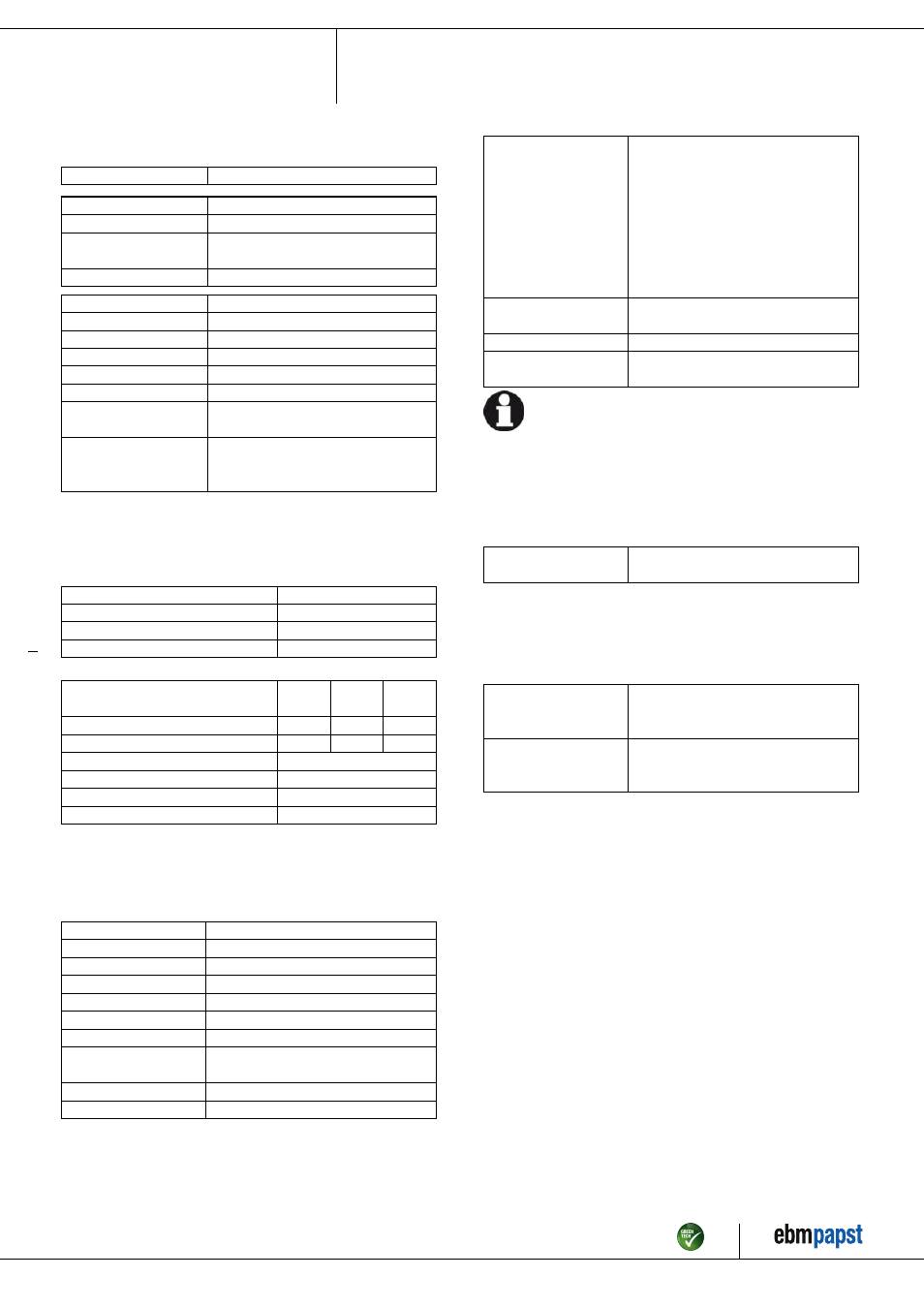
3.2 Nominal data
Motor
M3G074-CF
Phase
1~
Nominal voltage / VAC
230
Nominal voltage
range / VAC
200 .. 240
Frequency / Hz
50/60
Type of data definition
ml
State
prelim.
Speed / min
-1
1120
Power input / W
165
Current draw / A
1.28
Min. back pressure / Pa
0
Min. ambient temperature
/ °C
-25
Max. ambient
temperature
/ °C
60
ml = Max. load · me = Max. efficiency · fa = Running at free air
cs = Customer specs · cu = Customer unit
Subject to alterations
3.3 Data according to ErP directive
Installation category
A
Efficiency category
Static
Variable speed drive
Yes
Specific ratio
*
1.00
*
Specific ratio = 1 + p
fs
/ 100 000 Pa
Actual
Request
2013
Request
2015
Overall efficiency η
es
/ %
49.3
25.1
32.1
Efficiency grade N
61.2
37
44
Power input P
ed
/ kW
0.13
Air flow q
v
/ m³/h
705
Pressure increase total p
sf
/ Pa
305
Speed n / min
-1
1545
Data definition with optimum efficiency.
The ErP data is determined using a motor-impeller combination in a standardised
measurement configuration.
3.4 Technical features
Size
200 mm
Material of impeller
Sheet steel, galvanised
Housing material
Sheet steel, galvanised
Direction of rotation
Clockwise, seen on rotor
Insulation class
"B"
Humidity class
F3-1
Mounting position
Any
Condensate discharge
holes
None, open rotor
Operation mode
S1
Motor bearing
Ball bearing
Technical features
- Output 10 VDC, max. 1.1 mA
- Tach output
- Motor current limit
- Soft start
- Control input 0-10 VDC / PWM
- Control interface with SELV potential
safely disconnected from the mains
- Over-temperature protected
electronics / motor
Motor protection
Thermal overload protector (TOP) wired
internally
Cable exit
Variable
Protection class
I (if protective earth is connected by
customer)
For cyclic speed loads, note that the rotating parts of the device
are designed for maximum one million load cycles. If you have
specific questions, contact ebm-papst for support.
3.5 Mounting data
For depth of screw, see chapter 3.1 Product drawing
; Secure the mounting screws against accidentally coming loose (e.g.
by using self-locking screws).
Strength class for
mounting screws
8.8
You can obtain additional mounting data from the product drawing if
necessary.
3.6 Transport and storage conditions
; Use the device in accordance with its protection type.
Max. permissible
ambient motor temp.
(transp./ storage)
+ 80 °C
Min. permissible
ambient motor temp.
(transp./storage)
- 40 °C
Item no. 51773-5-9970 · Revision 76115 · Release 2012-03-14 · Page 5 / 9
ebm-papst Mulfingen GmbH & Co. KG · Bachmühle 2 · D-74673 Mulfingen · Phone +49 (0) 7938 81-0 · Fax +49 (0) 7938 81-110 · [email protected] · www.ebmpapst.com