Eagle Microsystems LP4300 User Manual
Page 4
2.3 SITE SELECTION
1. Line power devices causing large inductive currents should not run off the same circuit as
the scale. Fluctuations in line voltage caused by such devices may result in display instability.
2. The hook-up cable to the read-out should not run close to other unshielded cables. Display
instability may result.
3. For best accuracy, a flat, level, and rigid surface is recommended to support the scale and ton
containers.
4. The area should be accessible for periodic cleaning.
2.4 INSTALLING
1. Clean the site area of dirt and debris.
2. With the bottom of the scale exposed, install the four leveling feet in the four corners of the scale.
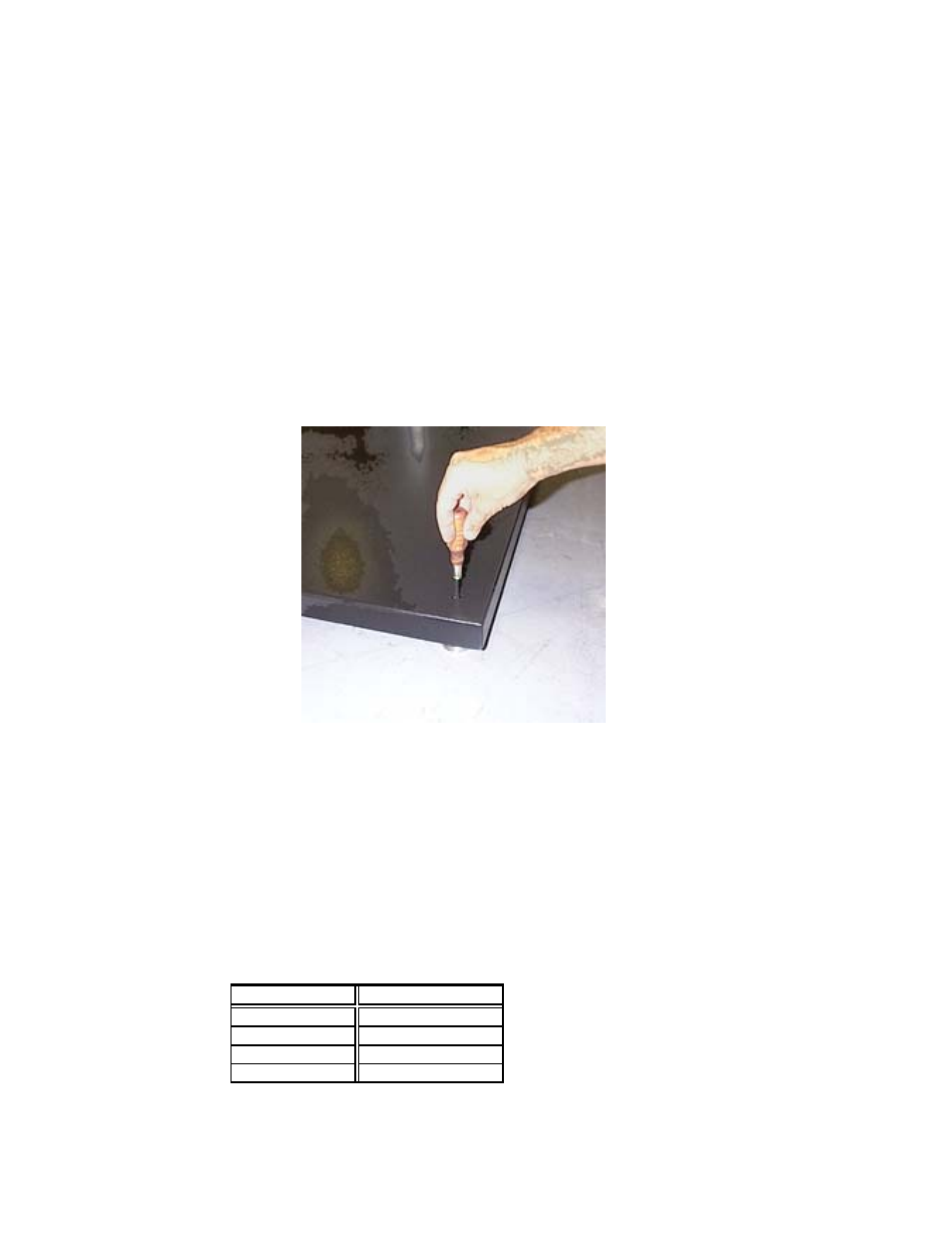
2.5 LEVELING
Corner detail showing easy leveling adjustments
with scale in place. A screw driver is the only tool needed.
1. For best scale performance scale should be level within 1/2 degree.
2. Check all corners for wobble and adjust leveling feet as if required, with a sctew driver through the
acess holes. (see photo)
.
2.6 HOOK-UP CABLE
Figure 1 shows the wiring connections necessary to attach the platform to the read-out instrument. The
color code and function are as noted.
C O L O R
FUNCTION
B L A C K
– EXCITATION
W H I T E
– SIGNAL
R E D
+ EXCITATION
G R E E N
+ SIGNAL
Fig. 1