Installation audio connections, Power connection – Drawmer DSL424 TwoPlusTwo Dynamics User Manual
Page 4
4
DRAWMER DSL424 O
PERATOR’S
M
ANUA
L
The DSL424 is designed for standard 19" rack mounting
and occupies 1U of rack space. Avoid mounting the unit
directly above power amplifiers or power supplies that
radiate significant amounts of heat and always connect
the mains earth to the unit. Fibre or plastic washers may
be used to prevent the front panel becoming marked by
the mounting bolts.
INSTALLATION
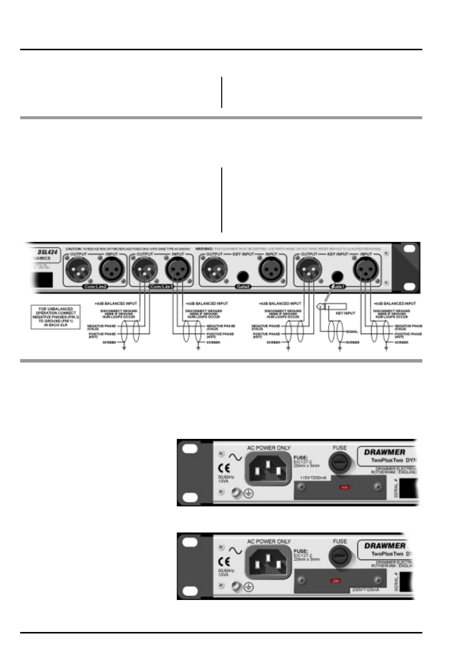
AUDIO CONNECTIONS
The inputs and outputs are electronically balanced on conventionally wired XLRs (pin 1 screen, pin 2 hot, pin 3 cold and
XLR shell is connected to chassis). The operating level is nominally +4dBu. Balanced use is recommended.
• Interference:
If the unit is to be used where it maybe exposed to
high levels of disturbance such as found close to a TV
or radio transmitter, we advise that the unit is operated
in a balanced configuration. The screens of the signal
cables should be connected to the chassis connection
on the XLR connector as opposed to connecting to
pin1. The DSL424 conforms to the EMC standards.
• Ground Loops:
If ground loop problems are encountered, never dis-
connect the mains earth, but instead, try disconnect-
ing the signal screen on one end of each of the cables
connecting the outputs of the DSL424 to the patchbay.
If such measures are necessary, balanced operation
is recommended.
The unit will have been supplied with a power cable suitable for domestic power outlets in your country. For your own
safety it is important that you use this cable. The unit should always be connected to the mains supply earth using this
cable, and no other.
If for some reason the unit is to be used at a mains input operating voltage which is different to that as supplied, the
following procedure must be carried out :
POWER CONNECTION
Disconnect the unit from the mains.
Remove the two self-tapping screws
that hold the voltage selection switch
cover-plate onto the rear panel.
Remove the cover plate and slide the
switch fully to its opposite end.
Rotate the cover plate one half turn,
(180 degrees) and refit the two screws.
Replace with a correctly rated fuse for
the selected operation voltage.
Re-connect to mains power source.
Never disconnect the earth
from the mains supply
115V Setting
230V Setting
1:
2:
3:
4:
5:
6: