Control description, Chapter 2 – Drawmer DMS-3 A2D2 AES Grade 1 Dual Output User Manual
Page 6
6
production from all of your analogue to digital devices. The
analogue input is fed simultaneously to two seperately
controlled outputs both in AES/EBU, SPDIF and TOSLINK
formats enabling a backup copy to be made of the signal, as
well as solving any connectivity problems and allowing signal
distribution.
The Drawmer DMS-3 A2D2 has been meticulously designed
to faithfully, and transparently recreate your analogue signal
in digital in as simple and intuative method as possible. A
high quality Burr Brown input stage has been incorporated,
coupled with the AES Grade 1 digital converted outputs,
making the A2D2 perfect for recording, mastering and post-
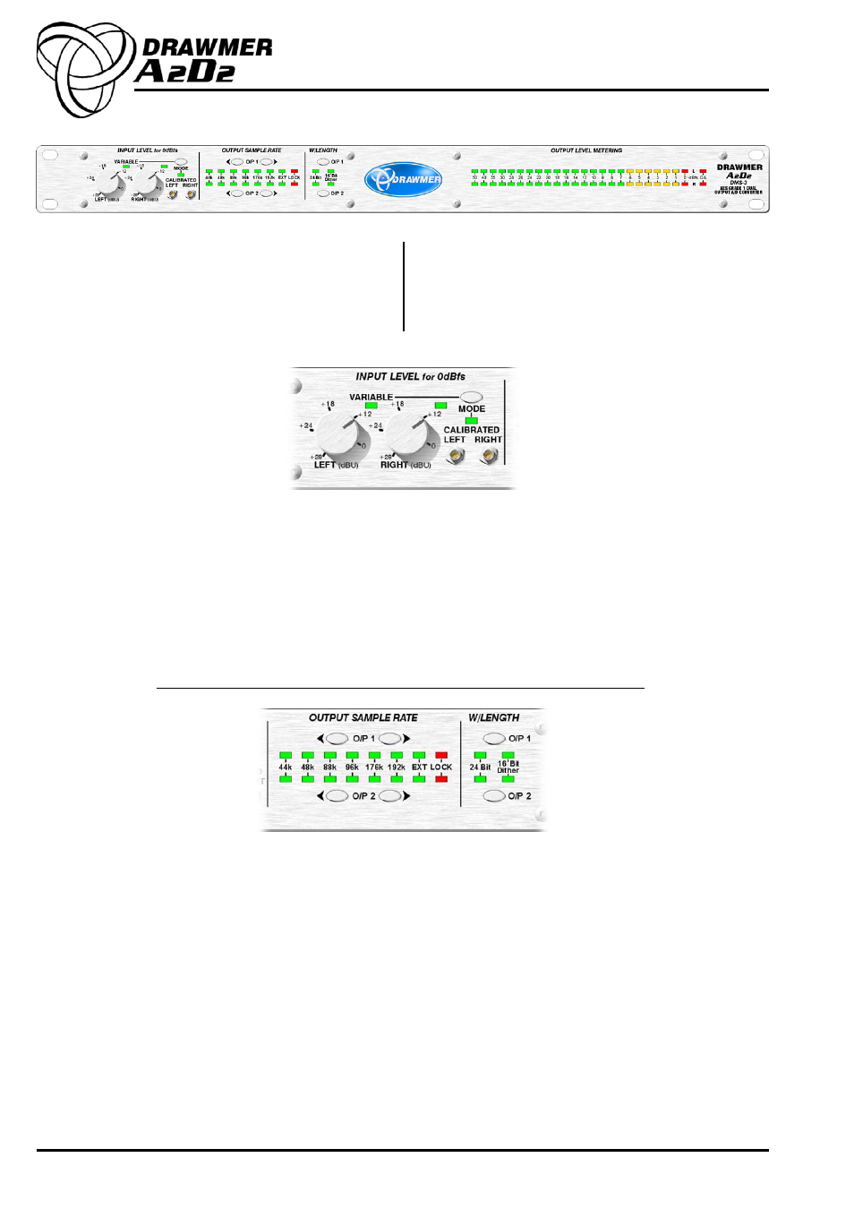
CONTROL DESCRIPTION
INPUT LEVEL for 0dBfs
MODE
One switch toggles between Variable and Calibrated modes of input level gain.
VARIABLE
In situations where the input levels can vary from place to place, such as in outside broadcasts, or
live venues, a variable input level has been provided, with accurate individual left/right control, to
provide quick setup. This ranges from +28dBU to 0dBU.
CALIBRATED
In the studio, where input and output levels will be calibrated and under better control, a calibrated
input gain option has been provided, in the form of very accurate (24 turn) left/right potentiometers
ranging from +28dBU to 0dBU. These require a small screwdriver to operate and so once set are
less likely to be accidentally adjusted.
CHAPTER 2
Output Sample Rate
The A2D2 has dual independant stereo digital outputs at different selectable sample rates from 44.1kHz to 192kHz - so it is
possible to have a main output at 192kHz with another at 44.1kHz as a low resolution copy.
O/P 1
The outgoing sample rate for O/P1 of the DMS-3 can be set using the two sample rate switches on the top
row - the left moving down rate and the right moving up, with a corresponding LED being lit to show the
current sample rate. The DSM-3 generates six Ultra Low Jitter sample rates - 44.1k, 48k, 88.2k, 96k, 176.4k
and 192k, all stable to <1ppm, and in addition can also operate at the sample rate generated by an external
source. With the Leds set to EXT the sample rate is set by the Wordclock input (as located on the rear panel).
A lock LED is provided on the front and operates when the EXT clock signal is strong.
O/P 1 also sets the sample rate of the three wordclock outputs on the rear panel.
W/Length
The top switch provides either 16 Bit Dither or 24 Bit operation for O/P1.
O/P 2
The outgoing sample rate for O/P2 can be set using the two sample rate switches on the bottom row and
operates in exactly the same way as with O/P1. When on EXT the sample rate is set using the same
Wordclock input as with O/P1.
W/Length
The bottom switch provides either 16 Bit Dither or 24 Bit operation for O/P2.