Sb-1-bi (built in) installation – Crown Verity SB-1 User Manual
Page 4
SB-1-BI (built in) Installation
The built-in version, which is offered in both L.P. and Nat. gas, is not supplied
with a hose, or a regulator. Regulators are supplied with all MCB-BI units. As
installations do vary in built-in applications, a qualified gas technician should
perform the connection of a gas supply line. Installation must conform with local
codes. Do not permanently fasten the SB-1-BI unit into it's opening, the unit may
need to be removed for servicing. Access to service points are gained from the
bottom of the unit. Make access possible when building the support structure.
Maintain clearances to combustibles as outlined below.
The gas supply inlet is located at the bottom of the manifold, inside the front
of the side burner cabinet. It is pre-fitted with a 3/8'" - 45 degree flare fitting and
is ready to receive 3/8" flared copper tubing.
The supply pressure must be regulated according to the pressures indicated on
the rating plate. The regulators that are supplied with all MCB-BI units are
compatible with SB-1-BI side burners and should be used. A "Tee" should be
installed downstream of the regulator and copper tubing can then be used to
connect the side burner.
It is very important that the side burner be connected to the correct type of gas
and is regulated at the correct pressure. The rating plate on all SB-1 units contains
this and other important information and must be observed.
Once connection to a supply line has been made, perform a leak check as
outlined in step 8 on pg. 2. Only then can you proceed to operate your side
burner.
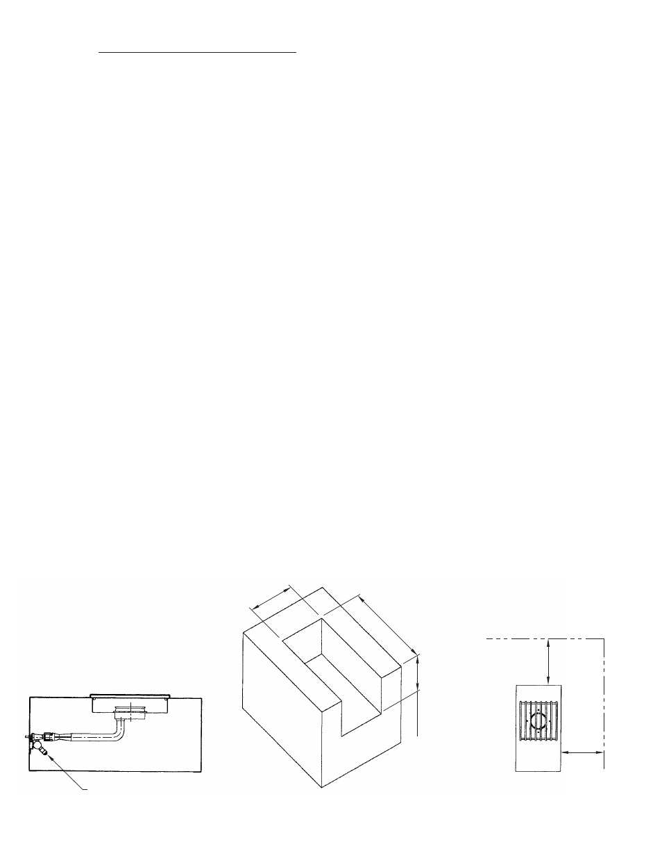
See diagrams below for gas inlet location, rough-in dimensions and clearances
to combustible materials. Note: minimum spacing between MCB's and side
burners in any configuration is 0".
CLEARANCES TO
ROUGH-IN DIMENSIONS
GAS INLET LOCATION
COMBUSTIBLE MATERIALS
12
1/
4"
MI
N.
12
1/
2"
MA
X.
22
3
/4
" M
IN
.
23
" M
A
X
.
9
5
/8
"
M
IN
.
9
7
/8
"
M
A
X
.
1
2
"
12"
TYP. ALL
SIDES
3/8" FLARE FITTING